|
|
| |
Some More Special Cases |
 |
The tensile test uses uniaxial stress;
pushing or pulling in just one direction This is a very special situation; the link above gets you there.
In real life,
all kinds of forces may act from all kinds of directions on specimen with all kinds of shapes. Before I go into this most
general case, we will give a few more special cases
a quick look. |
|
 |
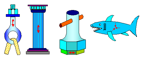
The figure below shows some more rather special stress states; you can for sure
cook up some more yourself. |
| |
|
|
|
 |
| Common stress states: |
|
| |
|
|
 |
What we have from left to right is: - Uniaxial tensile stress
- Uniaxial compressive stress
- Pure shear,
- Hydrostatic pressure
|
 |
The first two I have already dealt with.
The basic material parameter emerging from uniaxial testing was Young's modulus Y and Poisson's ratio n. |
|
 |
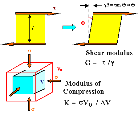
Pure shear and uniform compression are shown
below in a more scientific way. Pure shear means that the applied force is not at right angles to the surface it acts on,
but lies in the surface. The shear stress, customarily abbreviated by t and not s, is still force divided by area. |
|
| |
| |
 |
| Common stress states: |
|
| | |
|
|
 |
We can derive two new material parameters, a shear
modulus G and a compression modulus
K as shown. |
 |
Now we have four numbers describing the elastic
deformation of some material Where will it end? I have good and bad news for you: |
|
 |
So what is an isotropic material as opposed to an anisotropic one? Simple: The
properties of an isotropic material are independent of the direction. In other words, if you have some clump of material,
let's say a potato, and now cut tensile test specimen out of it (something like french fries), you get the same test results
no matter how you cut the specimen. Potatoes are isotropic materials; the taste of a french frie does not depend on how
you cut one out of the volume. |
|
 |
It is not the same for meat. Cutting with or across the grain makes a difference
in mechanical properties and texture / taste.
The same principle applies to crystals. In principle it matters how you
cut your specimen. Crystals tend to be anisotropic. You know this. Graphite, for example, gives extremely easily in one direction and is extremely tough in another. That's
why you can use it to lubricate things or to make extremely strong composites. |
 |
To describe properly what happens in a complex crystal when you subject it to
mechanical stress, you need indeed 21 numbers then called "elastic coefficients".
Sorry. But I have good news once more:
- All cubic crystals are isotropic - and that includes iron and steel.
- Poly
crystals with a random distribution of grains are isotropic: Anisotropies simply average out.
|
|
 |
If that is true (it is) logic dictates that if I have two
elastic parameters, I must be able to calculate
all the other ones. That's what we do, here is one result, relating the four moduli discussed so far. |
| |
|
| |
|
| G = |
Y
2(1 + n) |
» 0,4 E (for n
» 0,3) |
| K = |
Y
3(1 – 2n) |
» 0,8 E (for n » 0,3) |
|
|
| | |
|
|
 |
The shear modulus, by the way, is the convenient modulus when we go for plastic instead of elastic deformation. |
| | |
|
|
General Case of Deformation; Definition
of Normal and Shear Stress |
|
 |
In the most general case we have an arbitrarily shaped object that is not even
uniform but possibly composed of different materials - e.g. a potato with rotten spots, your car, you.
On this material
act all kinds of forces from all kinds of directions. Forces are vectors, illustrated
by arrows, and our potato about to be deformed might be illustrated like this: |
| |
|
|
|
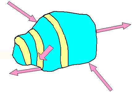 |
One example of general stress acting on
some inhomogeneous object |
|
| | |
|
|
 |
We only want to deform the object. We don't
want to move it and we don't want it to start spinning around some axis. That means that the vector sum of all forces must
be zero and so must be the torsional moments.
That makes the job somewhat easier but not really easy. |
 |
The first thing to realize is that the forces don't need to act exclusively perpendicular
on some surface anymore (like in tensile testing) but may have any arbitrary angle. That means we must expand the definition
of stress. |
|
 |
For that we look at some force F acting at some angle on
some surface A. If you like, you can describe the surface by a vector A that is perpendicular
to the surface it describes and has a magnitude (= length) that gives the surface areas. The figure below gives an idea
of that for some arbitrary internal area (in blue). |
| | |
|
|
|
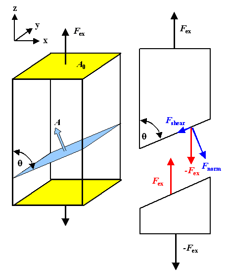 |
| Normal and shear stresses on planes inclined to a force. |
|
| | |
|
|
 |
We look at some plane inside an object inclined by some angle Q
to an acting force. We use this plane for a virtual cut through the object. Since the
cut is supposed to leave everything exactly as before, we must put some forces on both sides that are chosen in such a way
that exactly nothing happens. Since the external forces would move the two parts apart, these force must oppose the external
forces Fex. That implies that on our blue reference plane we must decompose Fex
into a component Fnormal normal to the plane, and a component a Fshear
contained in the plane.
That's rather easy to express in equations (provided you know the basics about vector math). |
|
 |
Next we calculate the stresses acting on the chosen plane. We have a stress given
by Fnormal divided by the area of the plane, which we call normal stress and always abbreviate
with s, and a stress given by Fshear divided by the area of the
plane, which we call shear stress and always abbreviate with t.
The area of the plane
contained inside the object is also easy to calculate.
For the forces and the area A we have |
| | |
|
| |
|
| Fnorm | = |
Fex · sin Q |
| | |
| | Fshear
| = |
Fex · cos Q |
| | |
| | A |
= |
A0/sin Q |
|
|
| | |
|
|
 |
With sex = nominal stress applied
to the object at large, the two stresses come out to |
| |
| |
| |
| s norm = |
Fnorm
A |
= |
Fex · sin2 Q
A0 | = |
sex |
· sin2 Q |
| | | |
| | |
|
| sshear = |
Fshear
A |
= |
Fex · sin Q · cos Q
A0 | = |
sex
2 |
· sin 2 Q |
|
|
| | |
|
 |
This was just doing some simple geometry. The results, however, are remarkable.
To see this, we plot the normal and shear components of the forces and the stresses they cause vs. the angle Q. |
| | |
|
|
|
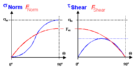 |
| Normal and shear stresses on planes inclined to the force. |
|
| |
|
|
 |
While the forces and the normal stress just change more or less smoothly between zero and
their maximum values, the shear stress has a maximum for Q
= 45 0 and is zero for Q = 0; 90 0.
Since, to get a little
ahead of myself, plastic deformation depends on shear stresses, we see already here why so much happens on planes roughly
at 45 0 to the direction of external stress. Those planes experience the maximum shear stress. |
 |
The long an short of this exercise was to establish what we do for the general
case: some force acts on some plane. We decompose that force into its three basic components and then produce three
stresses:
- A normal stress s norm given by the one
normal component of the force divided by the area.
- Two shear stresses tshear
given by the two components of the force in the plane divided by the area
Where that we will lead us we will see right below. |
| |
| |
|
General Case of Deformation; Tensor Formulation |
 |
If we look back at the general problem sketched above,
the first thing we do is to subdivide the potato or whatever else is under investigations into lots of (differentially)
small cubes. Some forces act on all six sides of all these cubes. We don't know these forces offhand but must calculate
them from the external forces acting on the outside of the potato. It ain't easy, so let's first look at what will happen
in a general way. |
| |
 |
Here is a complete picture of what one finds for one
of all the many cubes we are now considering. On other cubes the direction and length a of all the arrows might be different
but the general situation is the same. |
|
| |
| |
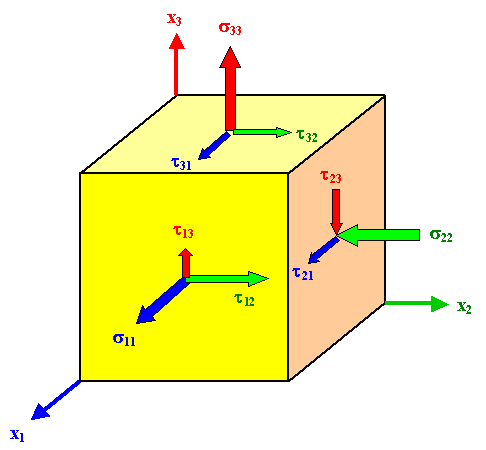 |
| General stress situation for any stressed (differentially) small cube. |
|
| | |
|
|
 |
On each of the six planes we have three acting stresses; one normal stress and two shear stresses.
Note that the arrows indicate the directions of the acting force components since stresses
are not vectors - they are something worse - even so they are shown as arrows here.
A coordinate system with an x1
, x2 and x3-axes as shown allows to sort the whole mess; the rules
are.
- si,j and ti,j denote normal
and shear stresses, respectively.
- The indices run from 1 to 3 and have a defined meaning:
i indicates the plane by giving the number of the coordinate axis perpendicular to it.
j indicates the direction of the force component |
|
 |
Here is an example: t2,3
is the shear stress on the plane perpendicular to the x2 axis caused by the force component
in x3 direction. |
 |
The thing to do now is to write all the components of the stress as follows: |
| |
|
| |
|
|
sij(x1, x2, x3) =
| æ
ç
è |
s11 t12
t 13
t21 s22 t23
t31 t32 s33 |
ö
÷
ø |
|
|
| | |
|
|
|
| sij(x
1, x2, x3) = |
æ
ç
è |
s11 t12 t13
t21 s22 t23
t31 t32 s33 |
ö
÷
ø |
|
|
| | |
|
|
 |
The nine numbers in this matrix describe all there is
to know about the stress state in our potato or whatever object we consider at the point given by the coordinates (x1,
x2, x3). |
|
 |
This reminds you (I hope) of a vector, a three-number thing that
describes certain physical properties like velocities at some point in space.
Good thinking. The nine-component matrix
above is a kind of generalized vector called a tensor of second rank. Vectors are simply tensors
of first rank, a scalar or simple number describing some physical properties like the temperature
at some point is is a tensor of zero rank. Before I go a bit more into tensor math, we do some simplifications. |
 |
When we do deformation science, we usually assume that our object does not move
or rotate. I squeeze my potato or whatever in such a way that its center of gravity stays put and it doesn't start to spin.
That implies that the sum total of all forces and all momentums is zero. If we consider that in detail, the result is: |
| | |
| |
| si j = s–i
–j | | |
| ti j = t
j i |
|
|
| | |
|
|
 |
There is some symmetry for the elements of the stress tensor. That is good - it means is that
we only need to know six numbers an not nine to be able to write down the full stress tensor at some point. What a relief! |
 |
In many cases, like the ones illustrated above, the stress tensor
has some symmetry that makes it simpler. Here are the examples from above plus a new one.
One number is enough for four cases; only pure torsion or shear needs two. |
| | |
| | |
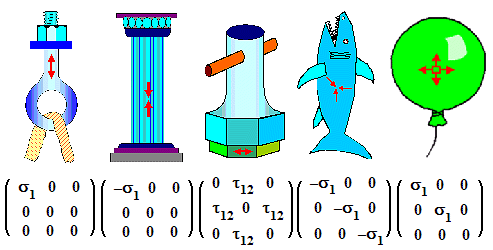 |
| Common stress states and the symmetry of the tensors going with them. |
|
| | |
|
 |
So what is a tensor
? The most simple way to look at a tensor is to realize that it connects two vectors in the most general and simple way.
|
|
 |
Let's look at the definition of stress once more to see what that means. We defined stress originally as "force divided by the cross-sectional area"
or s = F/A using a simple equation. The word "vector" never appeared
and without even telling you it, I assumed that the force is always perpendicular to the plane it acts on.
But here
we are a bit more sophisticated and realize that both F and A are vectors and that there is
no need for them to be always parallel. Since you cannot divide a vector by a vector, the simple definition of stress in
vector notation becomes. |
| |
|
| |
|
| | |
|
|
 |
If s would be a simple number or scalar, both vectors would
have the same direction, just the length would be different. This is too simple, of course. In full generality direction
and length could be different, meaning that every component of one vector will depend on all three components of the other
vector. Written out we have: |
| |
| |
| |
| Fx = sxx · Ax
+ sxy · Ay + s
xz · Az |
| Fy = syx · Ax
+ syy · Ay + s
yz · Az |
| Fz = szx · Ax
+ szy · Az + szz
· Az |
|
|
| | |
|
| |
 |
We need a nine-number entity to connect two vectors in the most simple
and general way. This thing we call a tensor (of second rank). |
 |
A hideous foreboding will now come up. "Where does this end", you might
ask. "Never" is the answer you will get from your friendly mathematician. Materials Scientists will be more forthcoming
and assure you that with tensors of fourth rank most everything can be done. Physicists tend to agree, but often invoke
at least four-dimensions for "Einsteinian" space or even11 if they are given to string theory. |
|
 |
You already know a tensor of fourth rank. In the backbone text I defined
Young's modulus as "how much stress
it takes to elongate a material by 0,01 %" or as stress divided by strain. Since in full generality Y
relates two tensors of second rank, it must be a tensor of fourth rank! In equations (with the components of Y
written as cijhk according to convention) that would be |
| | |
|
|
|
| s |
= |
Y · e | Simple equation |
|
| s 11 |
= |
c11 11 · e
11 + c11 12 · e12 + c11 13 ·
e13 + c11 21 · e21 +
c11 22 · e22
+ c11
23 · s23 + c11 31 · e31
+ c11 32 · e
32 + c11 33 · e33 |
| s12 |
= |
c12 11 · e
11 + ....
| | ..... |
| |
Spelled out in components |
|
| sij |
= |
cij kl · ekl
|
Indices notation with "Einstein" convention:
always sum over
common indices |
|
|
| | |
|
|
 |
When I showed that to my daughter (the one that studies literature), she remarked that she
had never seen anything more hideous in all her life. Well, beauty lies in the eye of the beholder. Nevertheless, I assume
that it will make you happy to know that the 81 components of Young's modulus proper (and then called elastic
coefficients) boil down to
- 21 components at most for the case of trigonal
crystals.
- 2 components for the case of cubic crystals.
- Two components for the case of (random) poly crystals.
- Between 2 and 21 for the rest
|
 |
The long and short is that for iron and steel as for most other simple because
cubic (and almost always poly-crystalline) metals, we get away with just two numbers. If we call them elastic coefficients,
or Young's modulus plus Poission's ratio, or shear modulus or whatever, doesn't really matter. You always can convert one set into another
one - if you know how to do it. |
|
 |
But don't kid yourself. What we just learned about Young's modulus applies to a lot of other
material properties, typically given to innocents as a simple number. Take the index of refraction, for example, the dielectric
"constant", or many others. They are actually tensors of various ranks and the do not always break down into just
one or two numbers. Worse, the components of these tensors may be complex
numbers, i.e. numbers that contain the square root of -1.
If you ever watched a three-dimensional movies, you had
to wear some special glasses. When you use those glasses, you are looking straight through rather complex tensors, to put
it this way. The tensor properties of materials are getting increasingly important and Material Scientists need to know
about this. |
 |
OK - now that we got the the simple stuff out of the way, we
can finally start with calculating how a potato deforms if you squeeze it. |
|
 |
Well, we won't. At least not here. Not only would I be hard pressed to do it, it is just too
difficult. Answers to the simple everyday questions of how something deforms if subjected to forces are notoriously hard
to get and the area of specialists with big computers and huge and complex software.
We will thus look only at some
very simple stuff somewhat later. |
| | |
|
© H. Föll (Iron, Steel and Swords script)


