| |
5.4.2 Dislocation, Plastic Deformation and Hardness
|
 |
We are getting close to our first
climax (we will experience multiple ones in due course, something you can look forward to). Here it comes. |
|
 |
Read the following sentence out loud to yourself
or whoever you can force listening to you, and then repeat it: |
| |
|
|
 |
Now stop hyperventilating and commence thinking.
Excuse me? You don't think that this is a Big Deal? You
are wrong. It is a big deal. We shall see why presently. |
 |
But I actually like
you to be a bit sceptical. Let's go through some of the questions that should have come to your sceptical mind:
|
 |
First question: "You
must be kidding! I might accept that one of those things, after running through the length of my large iron crystal, makes
a little step when it emerges on the other side. But his step is tiny! It is obviously just the size of an atom and that
would look small even at million-fold magnification. I assure you that if I bang a piece of iron with my hammer, you will
see the result with your unaided eye"! |
|
 |
Answer: You are absolutely right. If you bang
a piece of iron with a hammer, you don't need a microscope to see the deformation produced. Still, your piece of iron changes
its shape only because dislocations moved about. It's simply a hell of a lot of dislocations
that moved about, and their effects add up! At least a few million dislocations must move to make a dent of just about a
mm. Actually, a lot of the dislocations that react to your banging with your hammer will move somewhat but will not come
out on the other side. They get stuck inside. We have seen them with an electron microscope.
A good way to get some
idea of how many dislocations are around in your crystal is to measure their total length.
You may find something like 10.000.000 cm/cm3, or a total length of 1000 km
of dislocations inside a cm cubed. Now for you Americans: Around 600 miles in a crystal the size of a sugar cube. With that
many dislocations you get visible results! |
 |
Second question:
"OK—but what I get if I bang my piece of iron with my hammer depends
very much on how hard I bang. If I'm gentle, it might not deform at all—despite all those dislocations in there. So
how about that?" |
|
 |
Answer: You are right. And your question is
stupid naive, you could know better. Look at the stress
- strain diagrams I gave you! Plastic deformation commences as soon as the yield stress is reached. For lower stresses you only have elastic deformation. What that means should be clear: |
| |
|
|
 |
So, yes, you do need to bang with some force if something should happen. The harder the material, the more bang you need (remember?). |
 |
Third question: "Fine.
But where do all these dislocations come from? Does the crystal make them to achieve nirvana, like vacancies?"
|
|
 |
Answer: No! Never
ever. Crystals don't like to have dislocations anymore than they like grain boundaries or precipitates. They
would rather do without them.
But most crystals are not born perfect and with only a few exceptions they always contain
dislocations, like it or not.
The big exception, you guess it by now, are the huge man-made dislocation-free silicon crystals we use for electronics. They
are completely free of dislocations and as close to a perfect crystal in a state of a nirvana as a real crystal can be.
|
|
 |
In all natural crystals, including single
"gem stone" crystals, all
poly crystals, and pretty much all other man-made single crystal besides silicon (and germanium (Ge)), there are always dislocations.
In the "martensite" part
of hard steel (we'll get to that), you have a huge number of them. Their total length within one cm3 would cover
the distance earth - moon several times! |
|
 |
If you think that is amazing or just plain unbelievable, consider: The length
of your DNA molecule is a few meters, and the whole thing is cramped into a small nucleus just a few µm cubed. In terms
of length per volume it's comparable to dislocation length in heavily deformed crystals. |
 |
Fourth question: "Still,
one possibly could have crystals with many dislocations and crystals with not so many. Shouldn't they behave differently
if I bang them?" |
|
 |
Answer:
Yes, they should behave differently. And that's what they actually do.
The difference, however, would be only
noticeable at the very first moment of impact. That's so because dislocations are like rabbits. They multiply rabbitly if
you don't watch them (I know what I'm talking about; my daughters were into rabbits for many years). So when iron with just
a few dislocations is banged with a hammer, enough dislocations will be made rather quickly on the moment of impact, and
you will hardly notice a difference to iron with lots of dislocations.
Now if you
let me do a controlled experiment with my tensile
test machine. Then you can actually see what happens, this is shown in the figure below: |
| |
 |
| Stress - strain diagram of specimen without and with dislocations |
| The dark-blue curve is what you get if you start with no or few dislocations. If you stop
the experiment right after the peak, and then repeat it with the pre-deformed specimen, you get the red curve. |
|
|
 |
In the most extreme case, when you pull a completely dislocation free silicon
crystal at elevated temperatures where it is no longer brittle, we find a rather large yield stress in the first experiment. We simply
need more stress in this case then necessary to move dislocations because we first need to to produce them.
After the
first dislocations have formed, they rapidly multiply and the stress needed for further elongation comes down to substantially
lower values compared to the yield stress needed to initiate plastic deformation.
If we stop pulling the crystal right
after the peak that signifies dislocation production, the specimen looks pretty much the same, it is just a tiny bit longer.
It now contains a lot of dislocations and when we take it and repeat the experiment, it behaves quite "normal"
now. The yield stress is much lower and there is at best a small peak at the onset of plastic deformation. |
 |
Fifth question: "Good
enough" you might say, "but when I work iron, I can give it any shape. With
your dislocations running through, I would just get steps on one side". |
|
 |
Answer: True, but my dislocations can run
through the crystal in many ways. In fcc and bcc crystals there are actually 12 different possibilities or "glide systems",
only in hexagonal crystals you have less than that (3 or 6, depending a bit on details).
From tricky math (euphemism
for "I don't know how to do this") it can be shown that you can get any shape
if you have at least 5 different possibilities of shearing your work piece. So we have no problem for bcc or fcc iron. |
|
|
|
 |
Hexagonal crystals now, like
magnesium (Mg), cobalt (Co) or zinc (Zn); they have a bit of a problem. And sure enough, hexagonal crystals tend to be less
ductile, harder to get into shape, and easier to fracture eventually as we already ascertained early on in the context of
the Charpy test. We have answered another "why" question.
| |
 |
Now comes the sixth and tough question:
"One and the same piece of iron can be soft or hard, depending what I, the smith did to it. So if I hit some steel
with my hammer, the results can be quite different. Shouldn't it be always the same, if all that happens is that I make
dislocations and move them through the crystal?" |
|
 |
Answer: The answer can only be a resounding:
No! It should not be the same. |
|
 |
The reason is that it may be easy or difficult
for a dislocation to move through its crystal. If dislocation movement is so difficult that they can't move at all, the
crystal is brittle, no plastic deformation can take place.
That's why there are perfectly brittle crystals. The have dislocations like all crystals
but the buggers just can't move (at low temperatures). |
| |
We have the following easy relations:
- Dislocations can move easily and cover large distances: The material is ductile and soft.
- Dislocations cannot move easily but still cover large distances: The material is ductile and hard.
- Dislocations cannot move easily and get stuck after moving a bit: The material is still a little bit ductile and hard but comes across as rather brittle.
- Dislocations cannot move at all. The material is completely brittle
|
 |
Now get ready for the next climax: |
| |
Hardening iron and steel (or any metal
for that matter) simply means to put
obstacles in the way of the dislocations,
making it harder for them
to move through the crystal.
|
|
 |
The final seventh question:
Is it really true? Are you really sure that, to quote you: "Plastic deformation of
all crystals is done by moving dislocations through the crystal!"? |
|
 |
No. I'm not. Sorry. There are two more mechanisms, related to each other, that
could produce plastic deformation without dislocations. They are the (important) exceptions to the rule and called: There are people out there who would fight me for that statement, claiming that in both cases we have dislocations
at work, too. In a formal way they are right. In principle, however these modes of plastic deform our crystal, exactly the
same deformation could be achieved by moving special dislocations around in a special way. |
|
|
| |
|
But it also can be done without
dislocations; the results in the end are identical. Since whatever happens proceeds real fast, nobody has ever seen it happening
and thus we don't know "the truth" from experiments. We only know the results of what happened—and quarreled
about the detailed mechanism. It does appear, however, that the "no dislocation" faction is carrying the day |
|
 |
If you ever read anything about hard steel, the term "martensite
" came up for sure. Martensite forms by a shear transformation
, whatever that will turn out ot be. I'll look into that much
later.
More about the essence of twinning and martensite formation can be found right now in the science module.
|
 |
Now we are done. If you are still there, you have arrived at a first summit of
our long uphill climb. You now know the basics of engineering
properties like hardness. Time to open a bottle of the good stuff. |
| | |
|
 |
Back to work. We now can start answering a lot of those "why
" questions in a simple way: |
|
 |
Why does adding a little bit of carbon make iron
much harder?
Because it's making dislocation movement more difficult. |
|
 |
Why does deforming an initially soft piece
of steel make it much harder? (look at the relevant figure
again).
Because during the first deformation you produced a hell of a lot of dislocations and
many of them did not move out of the crystal but are still there. They are now hindering each other at moving. |
|
 |
Why is the steel soft again after tempering it for some time at high temperatures?
Because you produced vacancies that make the atoms mobile. The crystal now can go to
work, trying to achieve nirvana again. It rounds up all those defects that tie down the dislocations and kicks out most
of the dislocations too, if given time. The remaining ones now can move with ease. |
|
 |
Why do nanocracks in ductile materials not induce instantaneous fracture if a critical stress is surpassed; look at the first science module about fracture to appreciate that question.
Because
plastic deformation blunts the crack tip. This is not so obvious, so there is an extra science module about this |
|
|
|
 |
Why do some materials (including some steels) show the
"ductile-to-brittle transition syndrome, i.e. become more brittle at lower temperature with sometimes disastrous
consequences? | |
| | |
Because more vigorous vibrations of the atoms
in the crystal (that's what temperature is, remember?) helps
dislocations to move. If its cold, they move more sluggishly and my not be fast enough to "outrun" spreading nanocracks
that induce fracture. |
 |
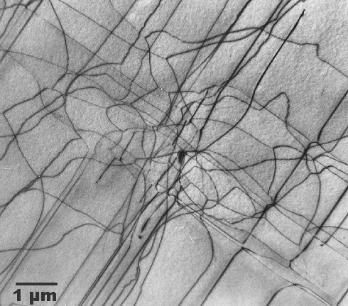
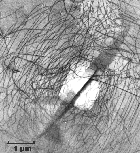
Let's finish this paragraph by looking at real dislocations (with
a transmission electron microscope or TEM). |
| |
 |
| Dislocations in silicon at medium magnification (TEM)
|
|
 |
I like these pictures because I took them many years ago. We are looking through the thin silicon specimen. Dislocations are imaged as black lines. The three-dimensional
dislocation arrangement is projected on a two-dimensional screen, just like the X-ray
pictures of your bones that your doctor shows you. |
|
 |
The top pictures show a kind of dislocation nest or cluster in otherwise perfect
silicon. Imagine it as a tangle of dislocation lines in three dimensions. If you estimate their total length, you find a
lot of length in a very small volume (look at the scales!).
By the way, these dislocations are there because somebody
touched that piece of silicon ever so lightly with a sharp needle, making a little indentation—the white rectangle
in the center. This is a bit like a hardness test, just on a much smaller scale. That produced the dislocation tangle—and
completely killed a microchip! |
|
 |
The lower picture shows dislocations in silicon that were produced because a thin
layer of something produced some stress. At room temperature, this only induces some elastic deformation. During some processing
at high temperatures, however, silicon became sufficiently ductile to allow production and movement of dislocations. Needless
to say that this wafer goes into the garbage bin. |
|
 |
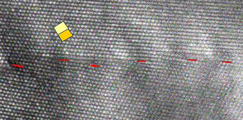
Of course, we can also look at dislocations at atomic resolution with HRTEM (always
provided the dislocation line is "edge-on"). Here is a picture: |
| |
 |
| Dislocations in silicon at atomic resolution |
| Red lines outline the ending crystal planes. Compare to the schematic
picture of a dislocation! |
|
|
 |
The lower picture shows a HRTEM picture of dislocations in silicon portrayed "edge-on"
just as drawn in the preceding chapter.
I love this picture too because
not only did I take it in 1979, it also happens to be once more among the very
first, if not the first HRTEM pictures of dislocations. It took until about 1975 before electron microscopes were good enough
to enable us for the first time to see the crystal structure directly. The red lines
indicate the lattice planes that end at the dislocation lines.
What you can see quite clearly is that even an enormous
density of dislocations (that's what we have here) does not really disturb the crystal all that much—you hardly
notice them if you don't look closely. |
 |
Why do I show pictures taken from silicon and not from iron or steel samples?
Because it is far more difficult to get this kind of pictures from (magnetic!) iron. You also don't get pictures as clear
as the ones shown here, since in iron there is always a lot of other stuff around. |
|
 |
Also, using my own pictures, I don't have to bother about getting copyrights from
all over the place. |
 |
What we have learned so far applies to the deformation of all
crystals, not just iron and steel. If we would be discussing swords made from most other metals, we would be almost done
now with the basics. |
|
 |
Iron, however, still has several additional
tricks up its sleeves. If you think what we covered so far was complicated (but enlightening, I hope), you're in for a surprise:
|
| |
|
The complications start now.
|
|
© H. Föll (Iron, Steel and Swords script)


