 |
At present, we have to make ends meet on our planet called Earth
or Terra, and with our sun, called Sun.
In all likelihood, this will not change in the foreseeable future. |
|
 |
"We" refers to people
or humans, since it appears we are the only species on earth using energy in
excess of what we need for just staying alive. We will see somewhat later or in this link
just how much energy we need for staying alive (in a certain style). |
|
 |
What most certainly will change in the foreseeable future is either
the way we supply ourselves with energy or the number of humans living (sort of) on
Terra. Note that neither the planet nor the other expressions of live on Terra would give a damn about strongly declining
numbers of Humans (they probably would be even very much in favor of that prospect).
|
 |
Since this Hyperscript is for that subgroup of the humans species that has a minimum
of brain power and is willing to use it (this excludes, for example, at least one American president), we know that the future energy needs of humankind will have to
be met by solar energy (in all forms: wind, "bio", solar heating, solar electricity,
waves, tides, ...) and, if you like it or not, nuclear energy. |
 |
So let's look at the most important hard facts first. They come from a host of
numbers and relations, some of which are contained in the following links. |
|
 |
World energy essentials: Read the article Future Global Energy Prosperity: The Terawatt Challenge of Nobel
prize winner Richard Smalley published in the MRS Bulletin 30,
2005, and the article "Powering the Planet"
of Nathan S. Lewis in the MRS Bulletin 32, 2007 to get a flavor of what it is all about. |
|
 |
Solar cell essentials
This is the solar cell module from "Einführung in dieMaterialwissenschaft II", with which you should be thoroughly familiar.
|
|
 |
Joules, Watts and kWh's
This is a "basic"
module within this Hyperscript, giving a few basic numbers and relations that you should get very well acquainted with.
Your life will depend on it! |
|
 |
Silicon for solar cells.
A module with a bit of the 30 year history around the efforts to generate cheap solar Si. |
|
 |
Poly Silicon solar cells.
Some facts and stories around the "multi crystalline" solar
cell. |
|
 |
Some (old) solar cell data.
"Old" refers to the fact that solar cell research, development and production grows so fast that the above module
from around 2004 is already quite outdated |
|
 |
FAQ's
around solar cells.
An "advanced" module of this Hyperscript with some more information about the applicability
of solar cells for energy production. It is only "advanced" because our task here is to look only
at the technology for making solar cells: not the application of solar cells. |
|
 |
Solarzellen und Materialwissenschaft A German Powerpoint Presentation to the general topic |
| | |
|
|
Solar Cell Primer
|
| | |
 |
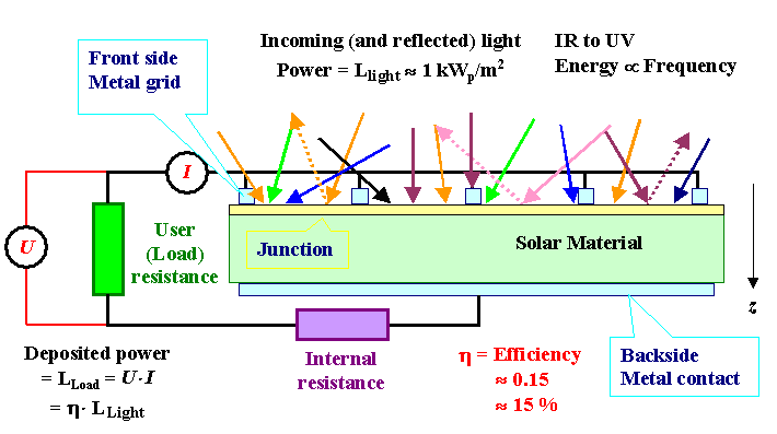
Now let's look at the basics of solar cells as shown in the figure below. |
| |
|
 |
Light:
We usually have a front side that absorbs the incoming light (there are a few solar
cell concepts where the light can be absorbed on both sides that we will neglect here). |
|
 |
The light has all kinds of frequencies according to its spectral distribution
- this is pretty much a given. |
|
 |
It is always coming from all directions because
there is always scattering in the air. Only if you have direct sun light, it will
come to a large extent from one direction , the sun. This has an important consequence:
You can focus direct sunlight but not indirect sunlight. Turn a large parabolic mirror
into the sun and put a relatively small solar cell in its focal point and you harvest the sun energy impinging on, for example,
1 m2 in a solar cell with an area of 1 cm2. This looks attractive in terms of saving
(expensive) solar cell area but the concept is not of much use in cloudy countries like Germany. Moreover, some of the savings
from needing fewer solar cells must now go to pay for all kinds of other gadgets, and you have the non-trivial problem of
keeping your solar cell cool. |
|
 |
A large part of the light is reflected if you just take a piece of semiconductor - after all,
Si is shiny and looks metallic because it
reflects light quite nicely. An ideal solar cell should look pitch-black - the fact that you usually can see
solar cells proves that they are not ideal in this context. Nevertheless, any solar cell must have some anti-reflection
technology on its front side; and how to do this (cheaply) is a large part of solar cell technology. |
|
 |
The light with the intensity Io(d , n) with d= angle of incidence and n=
frequency at the surface, that is not lost by reflection or absorption in the grid, penetrates into the semiconductor and is absorbed according to
|
| |
| I(d, n, z) |
= |
Io(d, n) · exp– (z/da)
|
|
|
|
 |
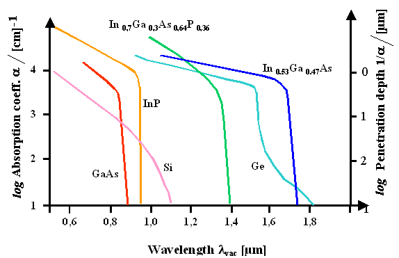
The parameter da(d, n)
is called the penetration depth of the light; it can be rather large for
indirect semiconductors like Si, e.g. 10 µm, but also quite small - a few nm - depending on the
semiconductor type and the frequency of the light. Obviously, only light that is absorbed inside the semiconductor can contribute
to energy conversion. |
|
 |
Quite often a quantity called absorption
coefficient a=1/da
is used; the figure shows some data (for perpendicular incidence). |
| |
|
 |
Junction:
Now we have generated exactly as may electron - hole pairs as we have absorped photons. We send some power
through the load - always in the form of a simple resistor - by extracting some of the
minority carriers produced by the light across a junction, which sweeps minority carriers that reach its space charge region (SCR) to the grid contact. This way we produce a photo current density
jP= number of minorities swept to the contact per s and cm2 and a photo potential determined by the junction potential. |
|
 |
Minority carriers generated by photons that do not reach
the junction (because, for example, they recombine in the bulk or at some internal surface)
obviously cannot contribute to the photo-induced current density j P. Changes for loosing minorities
to internal recombination grow if they have a long distance to cover (i.e. if they are produced far away from the junction)
or if they find many opportunities to recombine (Þ high defect density) on their
way to the junction. That's why we need "clean" Si for good solar cells. |
|
 |
We can make a suitable junction in many ways but usually we use a pn-junction. Schottky junctions,
for example, could be (and are) used, too, but the metal part absorbs light. One kind of solar cell even relies on an electrolytic
junction, but here we will not go into this. |
|
 |
The current (density) - voltage j(U) relationship of
an illuminated perfect pn-junction is described by our old pn-junction "master" equation |
| |
| j = |
æ
ç
è |
e · L · ni 2
t · NA |
+ | e · L · ni
2
t · ND
| ö
÷
ø |
· |
æ
ç
è |
exp | eU
kT | – 1 |
ö
÷
ø |
+ |
æ
ç
è |
e · ni · d(U)
t |
ö
÷
ø |
· |
æ
ç
è |
exp | eU
2kT |
– 1 |
ö
÷
ø |
– jPh |
| | |
| |
| |
| |
| |
| |
| |
| |
| |
| |
| |
| | |
( | j1 |
) | |
| |
| |
| |
( | j2 |
) | |
| |
| |
| |
|
|
|
 |
L is the diffusion
length of the semiconductor, nMin the minority carrier concentration (nMin=ni2/Ndop);
ni
=intrinsic carrier concentration, Ndop= doping concentration); t=life
time (t=L2/D);
D
=diffusion coefficient of carriers), kT=thermal energy, jPh
=induced photo current. |
 |
The two expression in front of the brackets are the reverse current densities
that come fron the bulk ( j1) and the space charge region ( j2
), respectively. |
|
 |
While the j2 term is often "negelcted" in text books,
here we must consider the influence of the space charge
region on the j(U) or, as it is often (sloppily) abbreviated, IV characteristics,
if we want to be half-way serious about solar cells - it is the decisive term! If you activate the link you will see (once
more?) that j2 >> j2 for Si and all other semiconductors with
bandgayp >»1 eV. |
|
 |
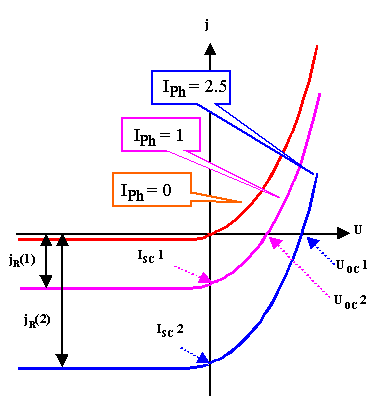
The resulting curves for three illumination intensities Io (including
Io =0=darkness) produce characteristics with short-circuit currents proportional to the illumination
intensity (or photon flux) and an upper limit of 1 carrier per photon. They look schematically like this: |
| |
|
|
 |
We can measure the characteristics simply by changing the load resistor Rload
from Rload=0 W=
short circuit conditions to Rload
Þ
¥=open circuit condition and keeping track
of the current and voltage in the external circuit. |
|
 |
From these measured IV-characteristics we learn a lot about our solar cell;
this will be treated in some detail in the next module. |
|
 |
Here we need to do an exercise to acquaint us again to the diode equation from above and its relevance for solar cells. |
|
|
|
|
 |
This is an important exercise! You should at least look at the solution, which will actually
be given in an advanced module! |
 |
Contacts:
We need electrical contacts to the front and back of the solar cell in order connect our constant
current source "solar cell" with the load. |
|
 |
On the front side this is either done by a grid of metal
contacts, which then always absorbs some of the incoming light without generating power, or by a layer of some transparent
conductor, which then will lead to problems with the resistivity. |
|
 |
At this point we finally must realize that solar cell technology is the art of making compromises - you can never get one parameter at the best possible value without
compromising others. This is true for purely technical parameters like in the task metioned above (find the best compromise
between series resistance and the area needed for contacts), but in particular for all
tasks where one of the parameters is money=costs. |
|
 |
An always unavoidable internal series resistance
RSE
is switched in series to the load and "eats up" a part of the voltage generated according to US=RSE
· I and thus reduces the efficiency. |
 |
Load:
We have a load that "consumes" the power provided. |
|
 |
The power provided by the solar cell in the external load (symbolized by a load resistor Rload ) is simply given by Uload ·
Iload. |
|
 |
The current flowing through Rload is the same as the current ISC
(=I in the characteristics) flowing through the solar cell, but U load ·
Iload is smaller than the voltage USC
of the solar cell (=U (or V) in the characteristics) by the voltage drop in the serial
resistor RSE, i.e. U load
=U – RSE · I . |
|
 |
Maximum power will only be delivered if the load is matched to the solar cell. Rload
must have a value that adjusts U and I in such a way that the point of maximum power on the
IV characteristics is met. |
|
 |
In other words: We need some "load management"
to always extract maximum power from our solar cell power plant. This looks more difficult than it really is; we therefore
won't come back to this point again. |
 |
Efficiency:
A solar cell is nothing but an energy transformer: Light energy goes in, electrical energy comes out. The question
of efficiency then always comes up quickly. |
|
 |
The relation between: input=light power to output=electrical power in the load depends on
the working point of the solar cell, i.e. on which point exactly on the
IV characteristics you run the system: solar cell plus external load. |
|
 |
There is a maximum efficiency h , however, that obtains
at the working point of maximum efficiency . It is easily extracted from the IV-characteristics
(just multiply I · V of the curve and plot it), and this maximum efficiency is meant when we talk
about the efficiency of a solar cell. |
|
 |
There is a strict theoretical
limit for h for any given solar cell; for Si solar cells h
» 25 % obtains. There are also practical limits; at present commercial Si
solar cells have h » 15 %. |
 |
Energy, Power, and Money
A solar cell exposed to sunlight produces power
=energy/time by converting the power contained in sunlight to electrical power
with an efficiency h. |
|
 |
The power contained in the sunlight varies with the daytime, the degree of cloudiness, and
the latitude. Maximum sunlight power is obtainable on a perfect cloudless day on the equator at high noon; it is around
1 000 W/m2 . |
|
 |
At the latitude of Kiel (54.12 o N) you have to multiply by cos(54.12
o)=0,586, so we get less sunlight than the people in the tropics (surprise!). But our solar cells stay cooler,
and that is good for the efficiency h. |
|
 |
When we characterize a solar cell (or a module of solar cells) in one
number, we give its "Wattpeak" Wp
nominal power, which, for a first guess, is Wp=h · 1 000
W/m2
. It's a little bit more complicated than that (things like "air
masses" AM 1.5
or AM 1 are involved). |
|
 |
The average power delivered by a solar cell, considering that the sun isn't always shining,
will be about 11% of the Peak power. 1 m2 of h=15 % solar cells
will thus produce per year an
amount of energy
Ey =1 000 · 0,15 · 0,11 · 24 · 365 Wh=145 kWh. |
|
 |
At present rates you pay about 15 € for this to your utility. If you count on
a life time of 20 years for your solar cells, a square meter should cost no more than about € 300 to
be competitive in the energy market. Of course, this kind of reckoning is naive, and the numbers have to be taken with a
grain of salt, but you get the basic picture in this context. More about parts
of this topic can be found in the link. |
 |
It is time for a little exercise: |
| |
|
| |
|
Modules
|
| | |
 |
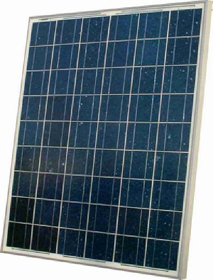
The typical Si solar cell - about (12 x 12) cm2 - is
not what you find on your roof: up there are solar modules, typically about (1.60
x 0.8) m2 or (1.60 x 1) m2 or any other size in the m2 range.
|
| |
|
 |
Typical module with 9 · 6=54
Si bulk solar cells |
|
|
 |
If the module contains Si
solar cells, about 50 - 100 individual solar cells are connected (by soldering) in series in a "string"; several strings are
connected in parallel. The series connection is absolutely necessary to raise the voltage to acceptable levels (it is far
more difficult in electrical engineering to deal with large currents and small voltages than vice verse) but causes a number
of problems on its own. |
|
|
 |
If the module contains thin film solar cells, long stripes of individual solar cells, about
1 cm wide, are connected in series in-situ, i.e. during the production process of the whole module in one fell swoop.
This causes a lot of problems on its own.... | |
 |
The total area of the solar cells in a module is always somewhat smaller than
the module area, and the top layer of the module (usually glass) that protects the solar cells from rain, bird shit, and
whatever else is in the air for a guaranteed 20 years, also reflects some of the incoming light. The efficiency of
the module is therefore always somewhat smaller than the efficiency of the solar cells. |
|
|
 |
Nevertheless, even if we count module technology under "semiconductor technology",
it is not quite as challenging to solder solar cells together than to make them. It might be just as expensive, however.
We will not go into this kind of module technology any more. |
|
|
 |
But let's not kid ourselves: if you make thin film solar cells with m2 sizes,
you must switch them in series even more urgently than with bulk Si solar. Typically, your individual solar cell
has now a size of (7 · 1.000) mm2, and switching these thin stripes in series must be done in-situ during manufacturing. There is no soldering involved anymore. We have a new, very complex,
and very challenging facet of semiconductor technology instead. |
|
© H. Föll (Semiconductor Technology - Script)


