 |
Let's consider a close packed lattice, and look at the close packed planes. |
|
 |
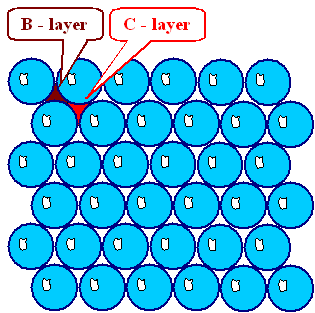
In a simple model using perfect spheres we have the following situation: |
| |
 |
 |
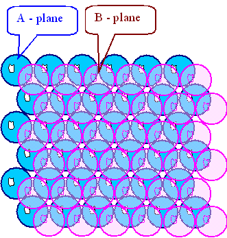
We take the blue atoms as the base plane for what we are going to built
on it, we will call it the "A - plane". |
 |
 |
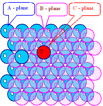
The next layer will have the center of the atoms right over the depressions of the A
- plane; it could be either the B - or C - configuration.
|
 |
Here the pink layer is in the "B" position |
 |
 |
If you pick the B - configuration (and whatever you pick
at this stage, we can always call it the B - configuration), the third layer can either be directly over the A - plane and then is also an A - plane (shown for one atom),
or in the C - configuration. |
 |
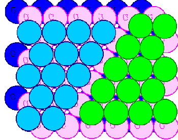
If you chose "A"; you obtain the hexagonal close packed
lattice (hcp), if you chose "C",
you get the face centered cubic lattice
(fcc) |
 |
 |
You can't have it both ways. If you start in the C position
somewhere (in the picture the green atoms) and on the A position somewhere else (light
blue), you will get a problem as soon as the two layers meet. |
 |
For varieties sake, and to be able to distinguish the layers better, the bottom A
layer here is in dark blue. |
|
 |
The stacking sequences of the two close-packed lattices therefore are |
|
 |
fcc: ABCABCABCA... |
|
 |
hcp: ABABABA... |
 |
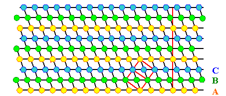
Looking at this sequences in cross-section is a bit more involved; it is best
done in a <110> projection of the fcc
lattice |
| |
| |
|
 |
Planes with the same letter are on lines perpendicular to the {111} planes, as indicated by thin black lines.
|
 |
The projection of the elementary cell is shown with red lines. |
| |
 |
We now remove parts of a horizontal {111} plane - e.g. by agglomeration
of vacancies on that plane - it shall be a C-plane here. |
| |
| |
|
|
|
|
 |
Now A and C- planes become neighbors
and relax into the configuration shown. |
 |
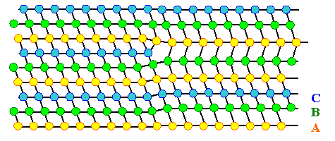
We produced a stacking fault because the stacking
sequence ABCABCA..
has been changed to the faulty
sequence ABCABABCA...
The stacking fault is between the large letters. |
 |
Stacking faults by themselves are simple two-dimensional defects. They carry a certain
stacking fault energy
g; very roughly around a few 100 mJ/m2. |
 |
The disc of vacancies obviously is bordered by an edge dislocation.
What is the Burgers vector of this dislocation? We shall see farther down. |
| |
| | |
 |
If we do not condense vacancies on a plane,
but fill in a disc of agglomerated interstitials, we obtain the following structure |
| |
| | |
| |
|
 |
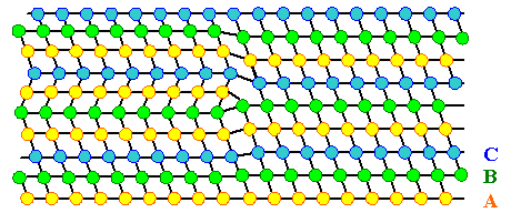
The stacking sequence ABCABCA...
again is faulty; it is now ABCABACABCA...
.
The stacking fault is between the large letters. |
|
|
 |
This is a different kind of stacking fault than the
one from above. |
| |
 |
For historical reasons, we call the stacking fault produced by vacancy agglomeration "intrinsic stacking fault" and the stacking fault produced by interstitial agglomeration
"extrinsic stacking fault". |
| |
 |
The extrinsic stacking fault also seems to be bordered by an edge dislocation. Again, what is the Burgers
vector? |
| |
|
 |
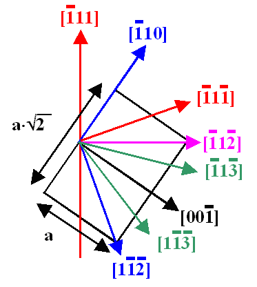
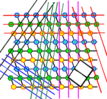
In order to determine the Burgers vector of the apparent dislocations bordering
the stacking faults, we must do a Burgers circuit or use the Volterra definition. For
this we must first be clear about the directions in the chosen projection. This is shown below. |
| |
 |
 |
Directions in the <110> projection
shown for the
elementary cell traced out on the right or above |
Traces of the (color-coded) planes (right angle to direction)
in the <110> projection and the elementary cell. |
|
 |
From a Burgers circuit or from a Voltaterra cut, we obtain the same result (Try
it! It is easier in this case to hop from atom to atom (instead from lattice point to lattice point); start at the stacking
fault). |
|
 |
The Burgers vector of these dislocations is b = ± a/3 <111>
- and this is not a translation vector of the fcc - lattice! Do not, at
this point, forget the distinction between lattice and crystal! |
|
 |
Dislocations with Burgers vectors of this type are called partial
dislocations, or more correctly, Frank partial dislocations,
or simply Frank dislocations. |
 |
This brings us to a general definition:
Dislocations with Burgers vector that are not translation vectors of the lattice are
called partial dislocations. They must by necessity border a two-dimensional defect,
usually a stacking fault. |
|
 |
This can be verified with the Volterra
construction if we add one element: Make a cut in a {111} plane and shift by a/3<111> perpendicular
to the plane. The element added is that we now include shift vectors that are not translation
vectors of the lattice, but vectors between equivalent positions
of the atoms. |
|
 |
Partial Burgers vectors and stacking faults thus may exist if the packing of atoms defining
the crystal has additional symmetries not found in the lattice. Check this
advanced module for an elaboration. |
|
 |
As stated in the definition of the Volterra cut-shift-weld
procedure, you now must add or remove material. The total effect is the creation of a Frank partial along the cut line and,
by necessity, a stacking fault on the cut part of the {111} plane. |
 |
We also see now that the primary defects which are generated by the agglomeration
of intrinsic point defects in fcc lattices are small "stacking fault loops".
|
| |
|
 |
Now we may ask a question: Can we produce stacking faults without
the participation of point defects? Indeed, we may - use the Volterra
definition to see how: |
|
 |
Make a cut on a {111} plane, e.g. between the A- and B-plane. |
|
 |
Move the B-plane so it is now in a C-position. No material must be removed or
added. |
|
 |
Weld together: You now have the stacking sequence ABCACABCA... instead of ABCABCA..,
i.e. you produced the stacking sequence of an intrinsic stacking fault. |
 |
The vector of the shift must be the Burgers vector of the partial dislocation
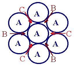
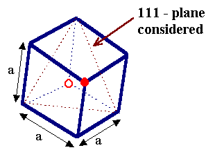
resulting from this operation as the boundary of the intrinsic stacking fault. This shift vector can be seen by projecting
the elementary cell on the close packed {111} plane where we did the cut. |
|
 |
 |
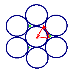 |
The displacement vectors
for producing stacking faults
with the Volterra construction.
We have all vectors pointing
from one "dent" to a neighboring one. |
The directions in the {111} plane.
If you superimpose the two red circles,
you have the
projection shown on the left. |
Each one of the red vectors would
move a {111} plane from
an A-position to a B
position
(marked by a green dot). |
|
|
 |
The relevant displacement vectors are of the type b = a/6<112>. (Check
it! It's good exercise for getting used to lattice projections). Dislocations with this kind of Burgers vector are called
Shockley
partial dislocations, Shockley dislocations, or simply Shockley partials. |
|
 |
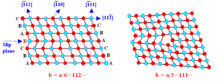
In our <110> projection, Shockley and Frank partials look like
this (after a picture from "Hull and Bacon"). The pictures
are drawn in a slightly different style, to make things a bit more complicated (get used to it!) |
| |
|
|
 |
You can't quite see the Shockley dislocation? Well, neither can I. But it is time to get used
to the fact that not all dislocations are edge dislocation, clearly visible in schematic drawings. We will encounter dislocations
that are far weirder and almost impossible to "see" in a drawing, or hard to draw at all. But nevertheless they
exist, possess a stress- and strain field described by the formulas from before,
and are just the real world inside crystals. |
 |
By now you are wondering if these partial dislocations are an invention of bored
professors? Well, they are not! They are more or less the only
kind of dislocations that really exist in fcc crystals (and some others)! |
|
 |
The reason for this is that perfects dislocations (with a Burgers vector of the type a/2<110>,
i.e. a lattice translation vector) will dissociate to form partial dislocations. This
is one kind of a possible reaction involving partial dislocations, which we are going to study in the next subchapter. |
© H. Föll (Defects - Script)


