 |
We now generalize the present view of dislocations as follows: |
|
 |
1. Dislocation lines may be arbitrarily curved
- never mind that we cannot, at the present, easily imagine the atomic picture to that. |
|
 |
2.
All lattice vectors can be Burgers vectors, and as we will see later, even vectors that
are not lattice vectors are possible. A general definition that encloses all cases is
needed. |
 |
As ever so often, the basic ingredients needed for "making" dislocations existed
before dislocations in crystals were conceived. Volterra
, coming from the mechanics of the continuum (even crystals haven't been discovered yet), had defined all possible basic
deformation cases of a continuum (including crystals) and in those elementary deformation cases the basic definition for
dislocations was already contained! |
|
 |
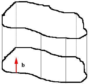
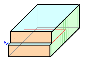
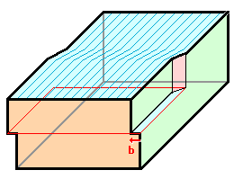
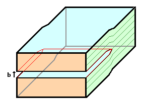
The link shows Volterra' basic deformation modes -
three can be seen to produce edge dislocations in crystals, one generates a screw dislocation. |
|
 |
Three more cases produce defects called "disclinations
". While of theoretical interest, disclinations do not really occur in "normal" crystals, but in more
unusual circumstances (e.g. in the two-dimensional lattice of flux lines in superconductors) and we will not treat them
here. |
 |
Volterra's insight gives us the tool to define dislocations in a very general way. For this
we invent a little contraption that helps to imagine things: the "Volterra knife",
which has the property that you can make any conceivable cut into a crystal with ease (in your mind). So lets produce dislocations
with the Volterra knife: |
 |
1.
Make a cut, any cut, into the crystal using the Volterra knife. |
|
 |
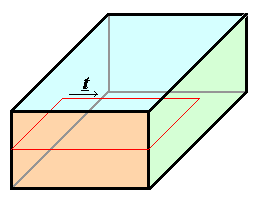
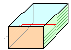
The cut is always defined by some plane inside the crystal (here the
plane indicated by he red lines). |
|
 |
The cut does not have to be on a flat plane, but we also do not gain much by making it "warped".
The picture shows a flat cut, mainly just because it is easier to draw. |
|
 |
The cut is by necessity completely contained within a closed line,
the red
cut line (most of it on the outside of the crystal). |
|
 |
That part of the cut line that is inside
the crystal will define the line vector t of the dislocation to be formed. |
| |
|
 |
2. Move the two parts of the crystal separated by
the cut relative to each other by a translation vector of the lattice; allowing elastic
deformation of the lattice in the region around the dislocation line. |
|
 |
The translation vector chosen will be the Burgers vector
b of the dislocation to be formed. The sign will depend on the convention used. Shown are movements
leading to an edge dislocations (left) and a screw dislocation (right). |
| |
|
 |
3. Fill in material or take some out, if necessary.
|
|
 |
This will always be necessary for obvious reasons whenever your chosen
translation vector has a component perpendicular to the plane of the cut. |
|
 |
Shown is the case where you have to fill in material - always preserving the structure of the crystal that
was cut, of course. |
|
 |
Left: After cut and movement. Right:
After filling up the gap with crystal material. |
|
|
|
 |
4.
Restore the crystal by "welding" together the surfaces of the cut.
|
|
 |
Since the displacement vector was a translation vector of the lattice,
the surfaces will fit together perfectly
everywhere - except in the region around the dislocation line defined as by the cut line. |
 |
A one-dimensional defect was produced, defined by the cut line
(= line vector t of the dislocation) and the displacement vector
which we call Burgers vector b. |
|
 |
It is rather obvious (but not yet proven) that the Burgers vector defined in this way is identical to the
one defined before. This will become totally clear in the following paragraphs. |
 |
From the Volterra construction of a dislocation, we can not only obtain the simple
edge and screw dislocation that we already know, but any dislocation. Moreover, from
the Volterra construction we can immediately deduce a new list with more properties of dislocations: |
|
 |
1. The Burgers vector for a given dislocation is always the
same, i.e. it does not change with coordinates, because there is only one displacement
for every cut. On the other hand, the line vector may be different at every point because
we can make the cut as complicated as we like. |
|
 |
2. Edge- and screw dislocations (with an angle of 90° or 0°,
resp., between the Burgers- and the line vector) are just special cases of the general
case of a mixed dislocation, which has an arbitrary angle between b
and t that may even change along the dislocation line. The illustration shows the case of a curved dislocation
that changes from a pure edge dislcation to a pure screw dislocation. |
| |
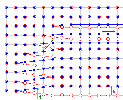 |
We are looking at the plane of the cut (sort of a semicircle centered
in the lower left corner).
Blue circles denote atoms just below,
red circles atoms just above the cut. Up on the right the dislocation is
a
pure edge dislocation, on the lower left it is pure screw. In between
it is mixed. In the link this dislocation is shown moving in an
animated illustration. |
|
|
 |
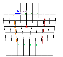
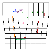
3. The Burgers vector must be independent from the precise way the Burgers circuit is done since
the Volterra construction does not contain any specific rules for a circuit. This is easy to see, of course: |
| |
|
|
| | Old circuit |
Two arbitrary alternative Burgers circuits.
The colors serve to make it easier
to keep track
of the steps. |
|
|
 |
4. A dislocation cannot end in the interior
of an otherwise perfect crystal (try to make a cut that ends internally with your Volterra knife), but only at |
|
 |
5. If you do not have to add matter or to take matter away (i.e. involve interstitials or vacancies),
the Burgers vector b
must be in the plane of the cut which has two consequences:
- The cut plane must be planar; it is defined by the line vector and the Burgers vector.
- The cut plane is the glide plane of the dislocation; only in this plane can it move
without the help of interstitials or vacancies.
. |
|
 |
The glide plane is thus the plane spread out by the Burgers vector b
and the line vector t. |
|
 |
6. Plastic deformation is promoted by the movement of dislocations in glide planes. This is easy
to see: Extending your cut produces more deformation and this is identical to moving the dislocation! |
|
 |
7.
The magnitude of b (= b) is a measure for the "strength"
of the dislocation, or the amount of elastic deformation in the core of the dislocation. |
 |
A not so obvious, but very important consequence of the Voltaterra definition
is |
|
 |
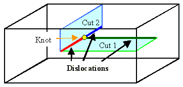
8. At a dislocation knot the sum
of all Burgers vectors is zero, Sb = 0, provided all line vectors
point into the knot or out of it. A dislocation knot is simply a point where three or more dislocations meet. A knot can
be constructed with the Volterra knife as shown below. |
 |
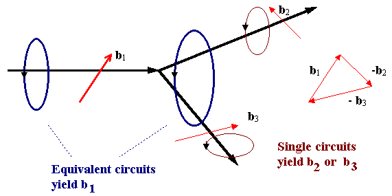
Statement 8. can be proved in two ways: Doing Burgers circuits or using
the Voltaterra construction twice. At the same time we prove the equivalence of obtaining b from a
Burgers circuit or from a Voltaterra construction. |
|
 |
Lets look at a dislocation knot formed by three arbitrary dislocations and do the Burgers circuit - always
taking the direction of the Burgers circuit from a "right hand" rule |
| |
|
|
 |
Since the sum of the two individual circuits must give the same result as the single "big" circuit,
it follows: |
| |
|
|
 |
Or, more generally, after reorienting all t -vectors so that they point into the knot:
|
| |
|
 |
Now lets look at the same situation in the Voltaterra construction: |
|
 |
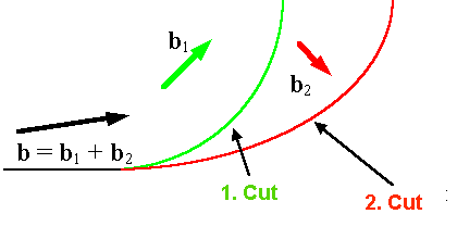
We make a first cut with a Burgers vector b1 (the green one in the illustration below).
|
|
 |
Now we make a second cut in the same plane that extends partially beyond the first one with Burgers vector
b2 (the red line). We have three different kinds of boundary lines: red and green where
the cut lines are distinguishable, and black where they are on top of each other. And we have also produced a dislocation
knot! |
| |
|
|
 |
Obviously the displacement vector for the black line, which is the Burgers vector of that dislocation,
must be the sum of the two Burgers vectors defined by the two cuts: b = b1
+ b2. So we get the same result, because our line vectors all had the same "flow"
direction (which, in this case, is actually tied to which part of the crystal we move and which one we keep "at rest"). |
 |
If we produce a dislocation knot by two cuts that are not
coplanar but keep the Burgers vector on the cut plane, we produce a knot between dislocations that do not have the same
glide plane. As an immediate consequence we realize that this knot might be immobile - it cannot move.
|
|
 |
A simple example is shown below (consider that the Burgers vector of the red dislocation may have a glide
plane different from the two cut planes because it is given by the (vector) sum of the two original Burgers vectors!). |
| |
|
 |
We can now draw some conclusion about how dislocations must behave in circumstances
not so easy to see directly: |
|
 |
Lets look at the glide plane of a dislocation loop. We can easily produce
a loop with the Volterra knife by keeping the cut totally inside the crystal (with a real
knife that could not be done). In the example the dislocation is an edge dislocation. |
|
 |
The glide plane, always defined by Burgers and line vector, becomes a glide
cylinder! The dislocation loop can move up or down on it, but no lateral movement is possible. |
| |
|
|
 |
What would the glide plane of a screw dislocation loop look like? Well there is no such thing as a screw dislocation loop - you figure that one out for yourself! |
|
 |
A pure (straight) screw dislocation has no particular glide plane since
b and t are parallel and thus do not define a plane. A screw dislocation could
therefore (in principle) move on any plane. We will see later why there are still some restrictions. |
 |
This leaves the touchy issue of the sign convention for the line vector t.
This is important! The sign of the line vector determines the sign of the Burgers vector,
and the Burgers vector, including sign, is what you will use for many calculations. This is so because for a Burgers circuit
you must define if you go clockwise or counter-clockwise around the line vector, using the right-hand convention. We will go clockwise! |
|
 |
The easiest way of dealing with this is to remember that the sum of the Burgers vectors must be zero if
all line vectors either point into the knot or away from it. |
|
 |
As long as only three dislocations meet at one point, there is no big problem in being consistent in the
choice of line vector and Burgers vectors, once you started assigning signs for the line vectors, you can throw in the Burgers
vector. There is however no principal restriction to only three dislocations meeting at one point; in this case the situation
is not always unambiguous; we will deal with that later. This is not as easy as it seems. We will do a little exercise for
that. |
|
 |
Last we define: The circuit is to close around the dislocation; the circuit in the reference crystal then
defines the Burgers vector. |
| |
|
© H. Föll (Defects - Script)
