 |
The smelting
and forging of
metals marks the beginning of civilization - the art of working metals was for thousands
of years the major "high tech" industry of our ancestors. |
|
 |
Trial and error over this period of time lead to an astonishing degree of perfection, as can
be seen all around us and in many museums. In the state museum of Schleswig-Holstein
in Schleswig, you may admire the damascene
blades of our Viking ancestors. |
|
 |
Two kinds of iron or steel were welded together and forged into a sword in an extremely complicated way;
the process took several weeks of an expert smith's time. All this toil was necessary if you wanted a sword with better
properties than those of the ingredients. The damascene technology, shrouded in mystery, was needed because the vikings
didn't know a thing about defects in crystals - exactly like the Romans, Greek, Japanese (india) Indians, and everbody else
in those times. |
|
 |
You might enjoy finding and browsing through several
modules to this topic which are provided "on the side" in this Hyperscript. |
 |
Exactly why metals could be plastically deformed, and why the plastic deformation properties could be changed to a very large degree by forging (and
magic?) without changing the chemical composition, was a mystery for thousands of years. |
|
 |
No explanation was offered before 1934, when Taylor,
Orowan and Polyani
discovered (or invented?) independently the dislocation. |
|
 |
A few years before (1929), U. Dehlinger
(who, around 1969 tried to teach me basic mechanics) almost got there, he postulated so-called "Verhakungen"
as lattice defects which were supposed to mediate plastic deformation - and they were almost, but not quite, the real thing. |
 |
It is a shame up to the present day that the discovery of the basic scientific principles governing
metallurgy, still the most important technology of mankind, did not
merit a Nobel prize - but after the war everything that happened in science before or during
the war was eclipsed by the atomic bomb and the euphoria of a radiantly beautiful nuclear future. The link
pays tribute to some of the men who were instrumental in solving one of the oldest scientific puzzles of mankind. |
 |
Dislocations can be perceived easily in some (mostly two-dimensional) structural pictures on
an atomic scale. They are usually introduced and thought of as extra lattice planes inserted in the crystal that do not
extend through all of the crystal, but end in the dislocation line. |
|
 |
This is shown in the schematic three-dimensional view
of an edge dislocations in a cubic primitive lattice. This beautiful picture (from Read?) shows the inserted half-plane
very clearly; it serves as the quintessential illustration of what an edge dislocation looks like. |
 |
Look at the picture and try to grasp the concept. But don't forget |
|
 |
1. There is no such crystal in nature: All real lattices are
more complicated - either not cubic primitive or with more than one atom in the base. |
|
 |
2. The exact structure of the dislocation will be more complicated.
Edge dislocations are just an extreme form of the possible dislocation structures, and
in most real crystals would be split into "partial" dislocations and look much more complicated. |
 |
We therefore must introduce a more general and necessarily more abstract definition of what
constitutes a dislocation. Before we do that, however, we will continue to look at some properties of (edge) dislocations
in the simplified atomistic view, so we can appreciate some elementary properties. |
|
 |
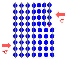
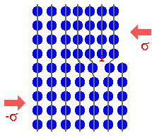
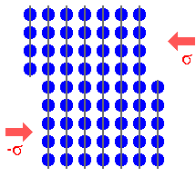
First, we look at a simplified but principally correct
rendering of the connection between dislocation movement
and plastic deformation - the elementary process of metal
working which contains all the ingredients for a complete solution of all the riddles and magic of the smith's art. |
|
 |
Generation of an edge dislocation
by a shear
stress |
|
 |
Movement of the dislocation
through the crystal
|
|
 |
Shift of the upper half of the crystal
after the dislocation emerged |
|
|
|
 |
This sequence can be seen animated in the link
|
 |
This calls for a little exercise |
|
|
 |
What the picture illustrates is a simple, but far-reaching truth: |
| |
Plastic deformation proceeds - atomic step by atomic
step - by the
generation and movement of dislocations |
|
|
 |
The whole art of forging consists simply of manipulating the density
of dislocations, and, more important, their ability of moving through the lattice. |
|
 |
After a dislocation has passed through a crystal and left it, the lattice
is complely restored, and no traces of the dislocation is left in the lattice. Parts of the crystal are now shifted in the
plane of the movement of the dislocation (left picture). This has an interesting consquence: Without
dislocations, there can be no elastic stresses whatsoever in a single crystal! (discarding the small and very
localized stress fields around point defects). |
 |
We already know enough by now, to deduce some elementary properties of dislocations
which must be generally valid. |
|
 |
1. A dislocation is one-dimensional defect because the
lattice is only disturbed along the dislocation line
(apart from small elastic deformations which we do not count as defects farther away from the core). The dislocation line
thus can be described at any point by a line vector
t(x,y,z).
|
|
 |
2. In the dislocation core the bonds between atoms are not in an equilibrium configuration, i.e. at their minimum enthalpy value; they are heavily distorted.
The dislocation thus must possess energy (per unit of length) and entropy. |
|
 |
3. Dislocations move under the influence of external forces
which cause internal stress in a crystal. The area swept by the movement defines a plane, the glide
plane, which always (by definition) contains the dislocation line vector. |
|
 |
4. The movement of a dislocation moves the whole crystal on
one side of the glide plane relative to the other side. |
|
 |
5. (Edge) dislocations could (in principle) be generated by the agglomeration
of point defects: self-interstitial on the extra half-plane, or vacancies on the missing half-plane. |
 |
Now we add a new property. The fundamental quantity defining
an arbitrary dislocation is its Burgers
vector
b.
Its atomistic definition follows from a Burgers circuit around the dislocation in the
real crystal, which is illustrated below |
|
|
|
|
 |
Left picture: Make a closed circuit that encloses the dislocation from lattice point to lattice point (later from atom to atom). You obtain a closed
chain of the base vectors which define the lattice. |
|
 |
Right picture: Make exactly the same chain of base vectors in a perfect
reference lattice. It will not close. |
|
 |
The special vector needed for closing the circuit in the reference crystal is by
definition the Burgers vector b. |
 |
It follows that the Burgers vector of a (perfect)
dislocation is of necessity a lattice vector. (We will see later that there are exceptions,
hence the qualifier "perfect"). |
 |
But beware! As always with
conventions, you may pick the sign of the Burgers vector at will. |
|
 |
In the version given here (which is the usual definition), the closed circuit is around the
dislocation, the Burgers vector then appears in the reference crystal. |
|
 |
You could, of course, use a closed circuit in the reference crystal and define the Burgers
vector around the dislocation. You also have to define if you go clock-wise or counter clock-wise around your circle. You
will always get the same vector, but the sign will be different! And the sign is very important for calculations! So whatever
you do, stay consistent!. In the picture above we went clock-wise in both cases. |
 |
Now we go on and learn a new thing: There is a second basic
type of dislocation, called screw dislocation. Its atomistic representation is somewhat
more difficult to draw - but a Burgers circuit is still possible: |
|
|
|
|
 |
You notice that here we chose to go clock-wise - for no particularly good reason
|
 |
If you imagine a walk along the non-closed Burges circuit, which you keep continuing
round and round, it becomes obvious how a screw dislocation got its name.
|
|
 |
It also should be clear by now how Burgers circuits are done. |
|
 |
But now we will turn to a more formal description of dislocations that will include
all possible cases, not just the extreme cases of pure edge or screw dislocations. |
| |
| |
|
© H. Föll (Defects - Script)