 |
The determination of the precise dislocation structure needed to transform a near-coincidence boundary into a true coincidence boundary
with some superimposed grain boundary dislocation network can be exceedingly difficult (to you, not to the crystal), especially
when the steps possibly associated with the grain boundary dislocations must be accounted for, too. |
|
 |
Nevertheless, the structure thus obtained is what you will see in a TEM picture - the
crystal has no problem whatsoever to "solve" this problem! |
 |
In order to get familiar with the concept, it is easiest, to consider the environment
of the S= 1 grain boundary, i.e. the boundary between two crystals with
almost identical orientation. |
|
 |
This kind of boundary is known as "small-angle grain boundary"
(SAGB)
, or, as already used above as "S1 boundary". |
|
 |
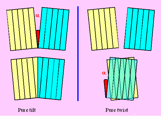
We can easily imagine the two extreme cases: A pure tilt
and a pure twist boundary; they are shown below. |
| |
|
|
 |
Obviously, we are somewhat off the S 1 position. Introducing grain boundary
dislocations now will establish the exact S1 relation between the dislocations (and something
heavily disturbed at the dislocation cores). The DSC-lattice as well the CSL are identical with the crystal
lattice in this case, so the grain-boundary dislocations are simple lattice dislocations. |
|
 |
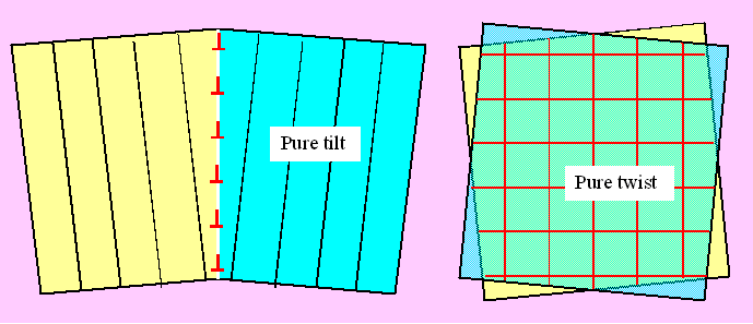
Introducing a sequence of edge dislocations in the tilt case and a network (not necessarily square) of
screw dislocations in the twist case will do the necessary transformation; this is schematically shown below |
| |
|
 |
This may not be directly obvious, but we will be looking at those structures in
great detail in the next paragraph. Here we note the important points again: |
|
 |
Between the dislocation lines we now have a perfect S1
relation (apart from some elastic bending). |
|
 |
All of the misfit relative to a perfect S
orientation is concentrated in the grain boundary dislocations. |
|
 |
We thus lowered
the grain boundary energy in the area between the dislocations and raised
it along the dislocations - there is the possibility of optimizing the grain boundary energy. The outcome quite generally
is: |
 |
Grain boundaries containing grain boundary dislocations which
account for small misfits relative to a preferred (low) S orientation, are in general
preferable to dislocation-free boundaries. |
|
 |
The Burgers vectors of the grain boundary dislocations could be translation vectors of one of the crystals,
but that is energetically not favorable because the Burgers vectors are large and the energy
of a dislocation scales with Gb2 and there is a much better alternative: |
|
 |
The dislocations accounting for small deviations from a low S orientation
are dislocations in the DSC lattice belonging to the CSL
lattice that the grain boundary S
endeavors to assume. Why should that be so? There are several reasons: |
|
 |
- Dislocations in the DSC lattice belong to both crystals since the DSC
lattice is defined in both crystals.
- Burgers vectors of the DSC lattice are smaller than Burgers vectors of the crystal lattice, the energy of several
DSC lattice dislocations with a Burgers vector sum equal to that of a crystal lattice dislocations thus is always
much smaller. With
Si
bi(DSC) = b(Lattice) , we always have
S
ib i2(DSC) << b2(Lattice).
This is exactly the same consideration as in the case of lattice dislocations split into partial
dislocations.
- A dislocation arrangement with the same "Burgers vector count" along
some arbitrary vector r produces exactly the same displacement (remember the basic Volterra definition
and the double cut procedure ).
|
 |
In other words: We can always imagine a low angle boundary of crystal lattice
dislocations that produces exactly the small misorientation needed to turn an arbitrary boundary to the nearest low S position and superimpose it on this boundary. |
|
 |
Next, we decompose the crystal lattice dislocations into dislocations of the DSC lattice belonging
to the low S orientation. |
|
 |
This will be the dislocation network that we are going to find in the real boundary! |
 |
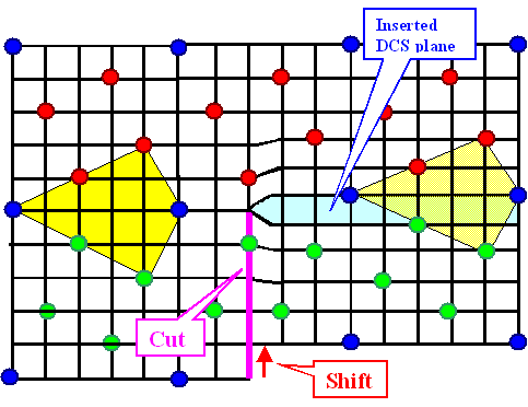
Lets illustrate this. First we construct another kind of DSC lattice dislocation,
very similar, but different to the one we had before. The coincidence points
are marked in blue, atoms of the two crystal lattices in green and red. |
|
 |
The plane of the cut now is perpendicular to the boundary and extends, by necessity, all the way to the
boundary. We produced a DSC edge dislocation with a Burgers vector perpendicular to the boundary plane (and a step
of the boundary plane). |
|
|
 |
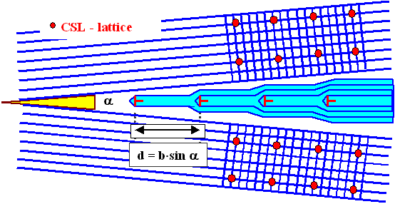
If we were to repeat this procedure at regular intervals along the boundary, we
obtain the structure schematically outlined below. |
|
|
 |
In essence, we superimposed a tilt component with a tilt angle a
that for small angles is given by is given by |
|
|
|
|
 |
with d = spacing of the DSC lattice dislocations and b = Burgers vector
of the DSC lattice dislocations. |
 |
In short, we can do everything with DSC lattice dislocations in a grain
boundary that we can do with crystal lattice dislocations. This leads to the crucial question alluded
to before: |
|
 |
How do we calculate
the DSC-lattice? As an example for the most general case of grain boundaries in triclinic lattices? Or even
worse: For phase boundaries between two different lattices (with different lattice constants)? |
 |
The answer is: Use the "Bollmann
theory or " O-lattice theory"
- it covers (almost) everything. |
|
 |
However, unless you are willing to devote a few months of your time in learning the concept and the math
of the O-lattice theory, you will encounter problems - it is not an easy concept to grasp. |
|
 |
We will deal with the O-lattice theory in a backbone
II section, here we note that the most important cases have been tabulated. Some solutions for
fcc crystals are given in the table: |
|
|
| S |
Generation | b from DSC-lattice |
| 1 | "Small-angle GB" |
a/2 <110>, possibly split into partials |
| 3 | Twin | a/6 <112>, a/3 <111> |
| 5 | 37° around <100> |
a/10 <130> | | 9 |
39,9° around <110> | 1/18<114>, 1/9<122>, 1/18<127>, |
| 19 | 26,5° around <110> |
a/38 <116>, a/19<133>, a/19 <10,9,3> |
| 41 | 12,7° around <100> |
a/82<41,5,4>, a/82<910>, ... |
|
|
 |
Interestingly (and very satisfyingly), the DSC lattice vectors belonging to the S
= 3 boundary are our old acquaintances, the partial
Burgers vectors associated with stacking faults in the crystal lattice. |
|
 |
This is but natural - a S = 3 twin boundary is after all a very close
relative to stacking faults. |
 |
Now a question might come up: S = 41 is not
exactly a "low S" value; and Burgers vectors of a/82<41,5,4> appear
to be a bit odd, too. So does this still make sense? Are boundaries close to a S41 orientation
still special and bound to have grain boundary dislocations? |
|
 |
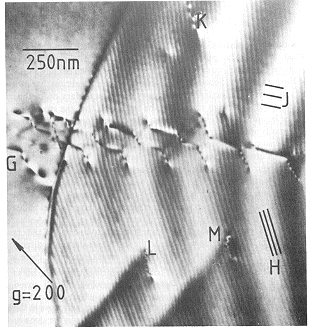
Only the experiment can tell . The following TEM picture shows a S
41 grain boundary (from Dingley and Pond, Acta Met. 27, 667, 1979) |
© H. Föll (Defects - Script)
