| |
 |
So-called "twin boundaries" are
the most frequently encountered grain boundaries in Silicon, but also in many other fcc crystals. This must be correlated
to an especially low value of the interface energy or grain boundary energy always
associated with a grain boundary. This becomes immediately understandable if we construct a (coherent) twin boundary. The
qualifier "coherent" is needed at this point, we will learn about its meaning below. |
|
 |
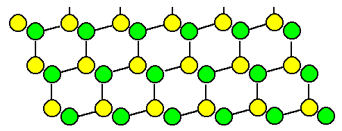
Lets look at the familiar <110> projection of the diamond lattice: |
| |
|
|
 |
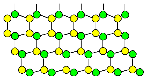
Now we introduce a stacking fault, e.g. by adding the next layer in mirror-symmetry (structural chemists
would call this a "cis" instead of a "trans"
relation): |
| |
|
|
 |
If we were to continue in the old stacking sequence, we would have produced a stacking
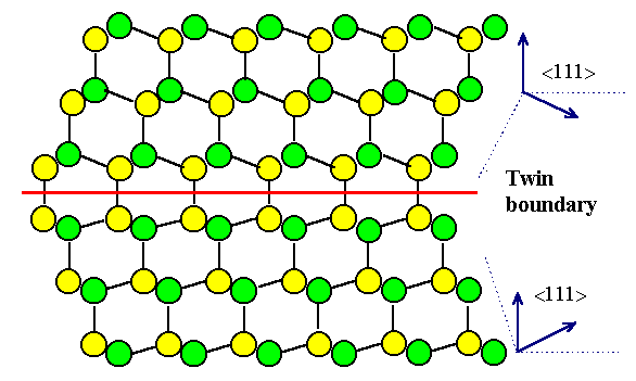
fault. However, if we continue with mirror-symmetric layers, we obtain the following structure without
changing any bond lengths or bond angles: |
|
|
|
 |
We generated a (coherent) twin boundary! This is obviously a special
grain boundary with a high degree of symmetry. |
 |
Now let's try to describe what we did in general
geometric terms. To describe the twin boundary from above or just any boundary geometrically,
we look at the general case illustrated below: |
|
|
|
 |
We have two arbitrarily oriented grains joined together at the boundary plane. We thus need
to define the "arbitrary" orientation and separately the boundary plane. |
|
|
 |
Choosing grain I as reference, we now can always "produce"
a arbitrary orientation of the second grain by "cutting" a part of grain I off - along the boundary plane
- and then rotating it by arbitrary angles a, b and
g around the x-, y- and z- axis (always defined
in the reference crystal, here grain I). | |
|
 |
Of course, the grain II thus produced would not fit together anymore with grain I. So we
simply remove or add grain II material, until a fit is produced. | |
|
 |
Alternatively, we could simply rotate the second crystal around one
angle a if we pick a suitable polar vector for that. |
|
|
 |
Specifying this polar (unit) vector will need two numbers or its direction
- e.g. two angles relative to the boundary plane or any other reference plane, and one
number for its length specifying the angle of rotation. | |
|
 |
In either way: three numbers then for the orientation part. |
|
|
| | |
|
 |
The boundary then is defined by 5 parameters: The three
rotation angles needed to "produce" grain II, and two parameters to
define the boundary plane by its Miller indices {hkl} in the coordinate system of the reference grain I.
|
|
 |
Why do we need only two parameters to define the boundary
plane? After all, we usually need three Miller indices {hkl} to indicate a plane in a crystal?
|
|
 |
Good question! We need only two numbers in this case because
here a unit vector with the right orientation given by {hkl} is sufficient -
the length, likewise encoded in {hkl}, does not matter. Since you need only two
angles between a unit vector and the coordinate axis' to describe it unambiguously, two
numbers are enough, even so they cannot be given straightforward in {hkl} terms. |
|
 |
The third angle is then always given by the Euler
relation |
|
|
| sin2a + sin2b + sin2g | = | 1 |
|
|
|
 |
Again, Miller indices do not only give the direction of a vector perpendicular
to a crystallographic plane, but also a specified length which contains the distance between the indexed crystallographic
planes - and that's why they need three numbers in contrast to a unit vector. |
 |
Thus, constructing a simple (coherent) twin boundary, looking
at it and generalizing somewhat, we learned a simple truth: |
| |
A (simple) grain boundary needs (at least)
5 parameters
for its geometric description |
|
 |
That was some basic geometry for a simple
grain boundary! For real grain boundaries we must add the complications that may prevail,
e.g.: |
|
 |
The grain boundary is not flat (not on one plane), but arbitrarily bent. |
|
 |
The grain boundary contains (atomic) steps and other local "grain boundary defects". |
|
 |
The grain boundary contains foreign atoms or even precipitates. |
|
 |
The grain boundary is not crystalline but consists of a thin amorphous layer between the grains. |
 |
Since all those (and more) complications are
actually observed, we must (albeit reluctantly) conclude: |
|
|
| Grain boundaries are rather complicated defects! |
|
| | |
|
|
Detailed Consideration of the Coherent Twin
Boundary |
| | |
 |
We can learn more about grain boundaries by analyzing our (coherent) twin somewhat more. While
we generated this defect by adding {111} layers in a mirror-symmetric way, there are other
ways of doing it, too: |
 |
We first consider the twin boundary as a pure twist boundary.
The recipe for creating a twist boundary following the general recipe from above is
as follows: |
|
 |
Cut the crystal along a {111} plane (using Volterras
knife, of course). |
|
 |
Rotate the upper part by 180° or 60° around an axis perpendicular
to the cut plane (= "twist") |
|  |
Weld the two crystals together. There will be no problem, everything fits and all bonds find partners. |
 |
This procedure is shown below. We are forced to conclude that we obtain exactly the same twin
boundary that we produced above! |
|
|
|
 |
Now lets look at the other extreme: We construct our twin boundary as a pure tilt boundary. The recipe for creating a tilt boundary following
the general recipe from above is as follows: |
| |
|
|
 |
Cut the crystal along a {111} plane (using Volterras
knife, of course) |
|
 |
Rotate the upper part by 70.53° around an axis perpendicular to the
drawing plane (= "tilt" the grain); i.e. use a <110>
direction for rotating. |
|
 |
Now, however, we must fill in or remove material as necessary. |
|
 |
Weld together. |
 |
This procedure is shown above; again we obtain exactly the same twin boundary we had before! |
|
 |
This is not overly surprising, after all the symmetries of the crystal should be found in the construction
of grain boundaries, too. |
|
 |
Well this is conceptually easy to grasp, it generates a major problem in the mathematical analysis of the
grain boundary structure. What you want to do then is to generate a grain boundary by some coordinate
transformation of one grain, and than analyze its properties with respect to the necessary transformation
matrix. If there are several (usually infinitely many) possible matrices, all producing the same final result,
you have a problem in picking the "right" one. We will run into that problem in chapter 7.3. |
| | |
|
Grain Boundary Orientation and Energy |
| | |
 |
Now lets look at the energy of the twin boundary and see if we can generalize the findings.
We are interested in answering the following questions: |
|
 |
Is the grain boundary energy (= the energy needed to generate 1 cm2 of grain
boundary) a function of the 5 parameters needed to describe the boundary? The answer, of course, will be yes, so now we ask: |
|
 |
For a given orientation, could a small change in the three angles describing
that orientation induce large changes in the energy? Asking a bit more pointedly: Are there orientations leading to boundaries
with especially small or large energies? Are there favorable and unfavorable orientations? |
|
 |
For a given orientation, are there possibilities to minimize the energy,
e.g. by changing the boundary plane? Are there favorable and unfavorable planes? |
 |
We will be able to answer these question to some extent by using our twin boundary. First lets
look at the energy of the (coherent) twin boundary as shown above. |
|
 |
We would expect a rather small energy per unit area, because we did not have to change bond
lengths or angles. We should expect that the energy of a (coherent) twin boundary should be comparable to that of a stacking
fault. |
|
 |
It is hard to imagine a boundary with lower energy and this explains why one always finds a lot of twin
boundaries in cubic (and hexagonally) close-packed crystals |
 |
Now lets generate a twin boundary with the "twist" or "tilt" recipe, but
with twist or tilt angles slightly off the proper values. Lets assume a twist angle
of e.g. 58° instead of 60°. We then make a boundary with a similar, but distinctly different orientation. |
|
 |
Try it! Can't be done. Nothing will fit any more; a lot of bonds must be stretched or shortened and bent
to make them fit. No doubt, the energy will increase dramatically. In other words: |
 |
The energy of a grain boundary may dependent very
much on the precise orientation relationship |
 |
Next lets imagine the generation of a twin boundary where the twist or tilt angle is exactly
right, but where the cut-plane is slightly off {111}. The result looks like the
schematic drawing below: |
| |
|
|
 |
Again, we have a hard time with the welding procedure. Some atoms will find partners with a slight adjustment
of bonds, but other are in awkward positions, e.g. the atoms colored blue in the above illustration. The
energy will be much higher than for a {111} plane - for sure. In other words: |
 |
The energy of a grain boundary may dependent very
much on the Miller Indices of its plane |
|
 |
We now can understand the meaning of the qualifier "coherent"
in connection with a twin boundary: Only twin boundaries on {111} planes are simple boundaries; they are called coherent
to distinguish them from the many possible incoherent twin boundaries with planes other
than {111}. |
| | |
|
Optimization of Grain Boundary Energies |
| | |
 |
From the last observation we can easily deduce a first recipe for optimizing,
i.e. lowering, the energy of a given grain boundary: |
|
 |
Decompose the grain boundary plane into planes with low energies. If that cannot be done, form at least
large areas on low-energy planes and small areas of connecting high-energy planes. In other words, approximate the plane
by a zig-zag configuration of planes. |
|
 |
This process is called facet forming or facetting,
the boundary plane forms facets. This is illustrated below. |
| |
|
|
 |
Grain boundary on low-energy plane (i.e. a {111} plane for a twin boundary).
The {111} planes are indicated by the dashed lines |
 |
Grain boundary on high -energy plane |
 |
Energy optimization by facetting on {111}. The total area increases somewhat, but the
energy decreases. |
|
 |
This is an important insight with far-reaching consequences: We need no
longer worry very much about the grain boundary plane! It is always possible to optimize the energy by facetting. |
|
 |
Facetting involves, of course, the movement of atoms. However, only small movements or movements over small
distances are needed, so facetting is not too difficult if the temperatures are not too low. So the
crystal has an option - it can change the boundary plane by moving a few atoms around. |
|
 |
Experience, too, seem to show that boundary planes are not very important: Grain boundaries, as revealed
by etching or other methods, are usually rather curved and do not seem to "favor" particular planes - with the
exception of coherent twins. This, however, is simply an illusion because the facetting takes place on such a small scale
that it is not visible at optical resolution. |
 |
We now must deal with the relation between the relative
orientation and the grain boundary energy. Two questions come to mind: |
|
 |
Are there any other low-energy orientations besides the rotations around
<111> or <110> that produces the low-energy twin boundary? |
|
 |
Is there a way to minimize the energy of a grain boundary that is close to, but not exactly in a low energy
orientation (some analogon to the facetting of the planes)? |
|
 |
This is not an easy question, because the crystal does not have an option of changing
the orientation relationsship. In principle it would be possible, but it would imply moving a lot of atoms -
all the atoms inside a grain - and that is rather unlikely to occur. |
 |
Answering these questions will lead us to an important theory for the structure
of grain boundaries (and phase boundaries) which will be the subject of the next sub-chapter. |
© H. Föll (Defects - Script)


