| |
| |
Interference Basics: The Double
Slit Experiment |
 |
X-rays are electromagnetic waves with wavelengths in the nanometer
(nm) region. Visible light, by contrast, has wavelengths somewhat below the micrometer (µm) region (about 400 nm - 700 nm, to be precise). That means that interference effects of X-rays take place on a nanometer scale - and that happens to be the atomic scale. |
|
 |
All of that is basic everyday knowledge, of course. Everybody with a halfway decent education knows the meaning
of the words in red italics above, no doubt. Except maybe our friends in America. I
mean, look at the kind of Presidents they elected (sort of)1.
We Germans,
by the way, have a physicist with a Ph.D degree as our top dog, who could write down the equations going with the statements
above even after having spend a mind-numbing evening with other heads of state, explaining to them a few basics about money.
Note that I name no names.
So maybe you Americans out there want to check the following modules first: |
| | |
|
| |
|
|
|
|
| |
| |
 |
Next, let's make sure you do not mix up X-ray diffraction, our topic here, with
"X-raying" something boring like you. That's what your doctor does when she takes an X-ray
image; on occasion we also do it in proper
science. X-ray imaging is just shadow casting with X-rays. Thick parts transmit less X-ray light than than thin parts. For
the same thickness, parts with heavy atoms inside transmit less X-ray light than parts with light atoms inside - that's
why we can see your bones. That's about all there is to know about X-ray imaging.
X-ray imaging is a powerful but trivial
technique compared to X-ray diffraction! |
| | |
 |
OK - let's get going. The basic experiment, or the paradigm of interference, is
the double slit experiment. Imagine an opaque plate with two fine slits, parallel
and close to each other, that will transmit light or, to be more general, any wave you care to consider. The width of the
slits and the distance between the slits should be larger but still comparable to the wavelengths of the waves considered.
For visible light, a few micrometers (µm) would be fine. |
|
 |
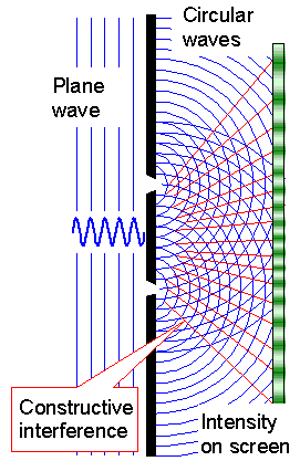
The basic "trick", also known on as Young's
principle (same Young as in Young's modulus, by the way), is to assume that an incoming
plane wave, upon hitting small objects like the slits, will
continue by producing a spherical (or here circular / cylindrical) wave around the object or obstacle. Behind the slits
we thus draw in circular waves as shown below. |
| |
| |
| |
 |
 |
| Principle | Real experiment |
| Double slit interference experiment. | |
| | |
|
|
 |
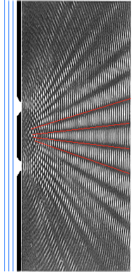
The blue lines indicate the maximum of the wave at some instance in time. Shown
is a cross-section at right angles to the slits. The circular waves emanating from the slits would be cylindrical in three
dimensions. The red lines indicate where constructive interference produces high intensities.
The experiment shows waves
in water, behaving exactly as predicted. |
 |
The two circular waves from the two slits superimpose and interfere. Constructive
interference leads to amplitude doubling along the red lines, in between total cancellation takes place. On a screen somewhere
behind the slits one would see a sequence of broad lines as indicated. |
|
 |
Now make three, four, many slits at equal distances - and you have a diffraction grating; a rather basic optical device. Instead of broad lines you now get fine and sharp
lines on your screen. Since the position of these interference lines are different for different wavelengths, white light
will produce a complete "rainbow" spectrum at each line.
A rainbow, by the way, is nothing but an interference
phenomenon; look it up yourself. |
 |
Making a diffraction grating for visible light is simple because the wavelengths
are huge (as seen from the viewpoint of atoms). Take a diamond with a fine tip and use it to just make parallel scratches
on a glass plate. You have made a 1-dim. diffraction grating. Or take a piece of textile with a fine weave (e.g. the kind
of fabric used for old-fashioned umbrellas) and you have a 2-dim. diffraction grating. Not a very good one but looking through
it at a bright light source (street light) will produce some spectra produced by interference. |
|
 |
How about making diffraction gratings for X-rays or electron "waves"
with sub-nm wavelengths? Scratching with diamonds or whatever won't do anymore.
But we don't need to worry. Mother Nature
has provided us with a wealth of suitable gratings at just the right dimensions. We just don't call them gratings anymore,
we call them crystals. |
| |
| |
|
Interference at Lattices
|
 |
A crystal can be seen as a diffraction grating in three dimensions
as shown below. When we shine a plane wave with suitable wavelengths on a crystal, any atom can be seen as an obstacle.
When an atom is hit by an incoming beam, it produces a spherical wave with a small amplitude. An intensive X-ray beam thus
can excite many atoms to produce spherical waves, which we now have to superimpose and see what we get. |
| |
| |
| |
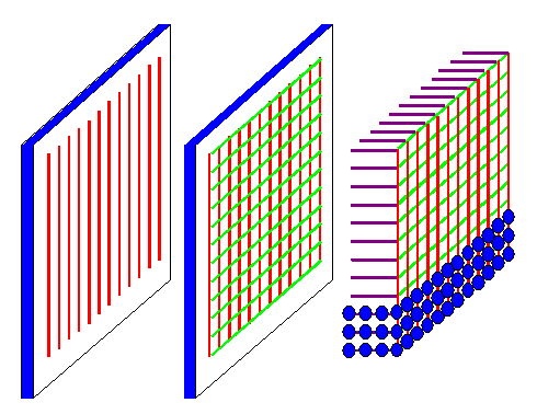 |
| Diffraction gratings in 1, 2, and 3 dimensions |
|
| |
| |
|
 |
Looking at the double slit experiment above, this seems to be a rather tough
job to do. Well, it is - if you are stupid enough to sit down with pencil and paper and start making drawings. We can do
that far easier. We have equations, after all.
As
it turns out after some juggling with the math, what happens when X-rays or electron "waves" hit a lattice
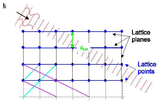
is extremely simple to understand. We do not even need to consider atoms. We just need to learn two
simple rules governing interferences at periodic structures like lattices as visualized below: |
| |
| |
| |
 |
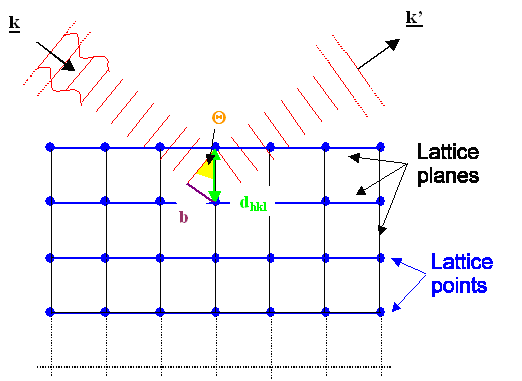 |
| The two possibilities of what can happen when a plane wave hits a lattice |
|
|
| |
 |
To understand those rules, we first consider
a plane wave, travelling in the direction marked by the "wave vector" k
as shown above. The length of the wave vector is given by |k| = 2p/l; l = wavelength, but that is of no importance here.
This wave hits some lattice that has a fixed orientation with respect to the wave.
Second, we consider one of the many lattice planes
inside the lattice. In the pictures above we pick the blue planes for ease of drawing. But we could equally well have picked
the black, blue, or magenta ones in the upper figure, or any plane not drawn in. |
|
 |
What happens to the incoming wave is:
- Either it just moves on and does not notice the lattice plane at all (upper figure), or:
- It gets reflected at the set of lattice planes considered (lower picture) and now
moves in the k' direction.
|
|
|
The second possibility - reflection - will only happen
if the angle between the incoming beam and the set of lattice planes has a specific value QB,
also known as Bragg
angle. The reason for this is that for all other angles interference will cancel everything.
The Bragg angle is given by a very simple equation: |
|
| |
| |
| sinQB | = |
n · l
2 · dhkl |
|
k – k' = g |
| Scalar form |
| Vector form |
with n = 1,2,3,...
dhkl = distance between {hkl} planes,
g = reciprocal lattice vector, = 2p/dhkl |
| |
| |
| |
|
 |
Even if you are not into math and equations, and don't see right away what those formulae
signify, you must admit that they couldn't be much simpler. |
 |
Now let's do an X-ray diffraction experiment. First we take a monochromatic beam,
with just one wavelength. We position a screen that lights up when hit by X-rays somewhere
above the crystal, and turn the experiment on. |
|
 |
What we we going to see on the screen? Not much. It is rather unlikely that one of the lattice
planes has accidentally the exact right orientation (or Bragg orientation) with respect to the incoming beam so that it
will reflect the beam. Depending on your luck, you see one or two reflection spots at best.
What you need to do now is:
|
| | |
Think! |
|
 |
Thanks. Here is what we could do:
- We rotate the specimen and thus change the angle of incidence systematically. At some angles some planes are in the
Bragg orientation, the beam gets reflected and produces a signal. Recording those angles allows to deduce what kind of lattice we have.
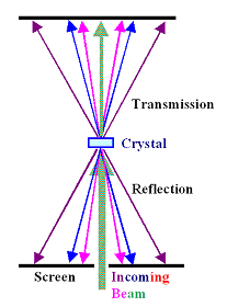
- We use a "colored" X-ray beam, i.e. a beam with many different wavelengths. Most lattice planes are in the
proper Bragg orientation for one of those wavelengths. We get many reflections, each one in a different "color".
Our screen, however, is "black and white" and won't show this.
- and 4. and 5. and so on: There are many other ways to do X-ray diffraction experiments.
|
| | |
|
|
|
|
 |
| Laue technique |
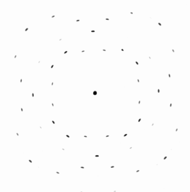
A typical Laue X-ray diffraction pattern | |
| | |
|
|
 |
The second mode it the most simple one and called "Laue
technique". The figure above shows how it is done. Note that
you do not have to rely only on "reflections" from the surface. If your beam completely penetrates the sample,
you may also look at what comes out on the other side. The actual diffractrogram shown (it's from silicon) tells even the
uninitiated that the crystal must have a cubic symmetry. |
 |
You may or may not have noticed that in looking at diffraction proper, so far
I never used the words "crystal" or "atoms", but only discussed "lattices", a somewhat abstract construct of how to have periodicity
in space. What that means is that the lattice of a real crystal is already enough to
tell us, in which directions we might expect some X-ray intensity, and in which directions we will never find any. |
|
 |
However, looking only at the lattice will not tell us
is how strong the reflected beams will be; how much intensity we will find in allowed
directions. Look at the picture above. Some reflections are darker than other, indicating more intensity. Some reflections
have an intensity of exactly zero and that's why you can't see them. I can't see them either but I know
that in some places reflections would be allowed.
So let's put that in large print |
| | |
|
|
|
The lattice of the crystal tells you
where you can find reflections.
The base (= atoms) of the crystal tells
you how intense those reflections will be.
| |
| |
| |
|
Interference at Crystals
|
 |
You get a crystal
by putting a certain arrangement of atoms - the base - at every point of the lattice. This would perhaps be a good time
to refresh your memory about the difference between lattices and crystals |
|
 |
Here is an example of what you are going to see for simple cubic crystals like
bcc iron (Fe), fcc gold (Au) and fcc-diamond silicon (Si). |
| | |
|
|
|
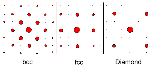 |
| Schematic intensities for simple cubic crystals. |
|
| |
| |
|
 |
The fine black points indicate allowed reflections with intensity = zero. Note that the diffraction
pattern always shows directly the symmetry of the crystal lattice. Here you see the four-fold or cubic symmetry of cubic lattices. |
 |
Concerning atoms and intensities, we now face two
tasks, and there are good news and bad news going with that. The good news are that the first task is very difficult. The
bad news are that the second task is pretty much impossible. What are those tasks?
- Calculate for a given crystal the intensities of the various reflections. In other words: Calculate the outcome of an
experiment, predict the so-far unknown diffraction pattern for a known crystal.
- Calculate for a given experimentally obtained diffraction pattern what the crystal that produced it consists of. In
other words: Calculate the unknown crystal from a known pattern. It's the inverse problem to the first one.
The first task is not easy to do "by hand" but doesn't present much problems with present-day computers.
If you ask a mathematician, she will tell you that the second task is simply impossible. The first task, in a much simplified
analogy, is like calculating the area contained in some geometric figure. Simple for a square or a circle, not so simple
for more involved figures. The inverse problem, calculating what kind of figure produces the area that you measured, simply
can't be done. Many different figures could have the same area, after all.
So let's not ask mathematicians but let's
ask Material Scientists or Mineralogists. They will tell you how it's done. |
|
 |
It's done by invoking some additional knowledge. You might know, for example, the chemical
composition of the crystal you want to analyze. You might know, for example, that your crystal is cubic (from the geometry
of the X-ray pattern) and that its chemical composition is NaCl. Now play around with
little spheres oft the proper size (you know how big those atoms are), and you will see that there aren't that many possibilities
to arrange those atoms in a cubic way. Now calculate the intensities you would get for each possibility (task No. 1) and
compare that to what you measured. If there is a match, you have the structure of your crystal.
For simple crystals
this is not difficult to do. However, for more complex crystals things get rather messy and tedious. Nevertheless, that's
how structure determination is done, and that includes those unbelievably complex biological molecules that are analyzed
nowadays. The big trick, actually, is to get the stuff to crystallize. The rest is "routine". |
|
 |
You have heard of that. One of the bigger scientific revolutions started in 1953 when Francis Crick and James Watson
(and let's not forget Rosalind Franklin and Maurice Wilkins) came up with the structure of DNA, using exactly the procedure outlined above (plus some lucky guesses).
The picture below is a model for a certain protein. All those ribbons symbolize strands of atoms. You don't have to know
details to appreciate that this is a pretty complex structure, unraveled by X-ray diffraction plus input from other methods. |
| |
| |
| |
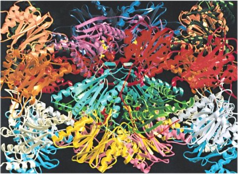 |
| Protein molecule structure |
| Source: ??? Some Res. Organization. Found it in the Net a long time ago. |
|
| |
| |
 |
The last thing to note is that everything we can do with X-ray beams because they
are waves, we can also do with electron beams since they are waves, too. To be sure, there are big differences in details
- like that electron beams tend to get stuck on very short distances (µm range), whereas an X-ray beam even makes it
through the bulk of me. But those are details, the big picture doesn't change. |
|
 |
While X-ray diffraction is the bread-and-butter part of structural Materials Science, electron diffraction is also a rather big game in town. Except that we don't call it "electron
diffraction" but "transmission electron microscopy".
Use the link to read on. |
| |
|
© H. Föll (Iron, Steel and Swords script)


