 |
The relation between the spacing of the dislocations and the tilt- or twist angle in the special
cases given was simple enough - but what about arbitrary small angle grain boundaries with twist and tilt components? What
kind of dislocation structure and what geometry should be expected? |
|
 |
As we have seen, the detailed structure of the network can be quite complicated and depends
on materials parameters like stacking fault energies. We can not expect to have a simple formula giving us the answers. |
|
 |
The relation giving the distance between dislocations in a boundary
and the orientation relationship for arbitrary low-angle orientations (meaning that the two rotation angles needed for a
general description are both small, lets say £ 10o - 15o) was
first given by Frank. It is Franks formula
referred to before. |
 |
Franks formula is derived in the
advanced section, here we only give the result. The low-angle grain boundary shall be described by: |
|  |
Its dislocation network consisting of dislocations with Burgers vectors b. |
|
 |
An arbitrary vector r contained in the plane of the boundary. |
|  |
A (small) angle a around an arbitrary axis described by the (unit) vector
l (then one angle is enough) that describes the orientation relationship between the grains. We may
then represent the rotation by a polar vector R = a · l |
 |
Franks formula then is: |
| |
|
|
 |
with B = sum of all the specific Burgers vectors bi
cut by r ; i.e. B = Si
bi. |
|
 |
Since the formula is formally applicable to any boundary, but does not make much sense for large angles
a (can you see why?) we only consider low-angle boundaries. Then we can replace sin
a/2 approximately by a/2 and obtain the simplified version |
| |
|
 |
Let's illustrate this: |
| |
|
|
 |
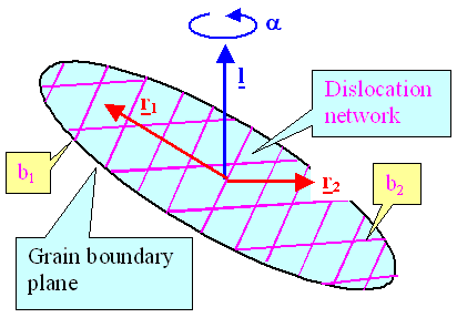
Shown are two vectors r1 and r2 contained in a boundary
plane with an arbitrarily chosen dislocation network consisting of two types of dislocations having Burgers vectors b1
and b2. |
|
 |
Franks formula ascertains that (r × l) · a
equals the sum of the Burgers vectors encountered by r, i.e. B = 2b2
+ 3b1 for r1, and B = 3b1
for r1 in the picture above. |
|
 |
This is a major achievement, but not overly helpful when you try to find out the geometry of the network
for some arbitrary boundary, because their is no simple and unique way of decomposing a sum of Burgers vectors into its
individual parts. |
 |
This "simple" formula, however, contains the special cases that we have considered
before, and leaves enough room for complications. It does not, however, say anything about preferred
planes or network geometries. For this one needs the full power of Bollmanns
O-lattice theory. |
 |
Franks formula is not applicable to large angle grain boundaries because the
distance between the dislocations would become so small as to be meaningless. |
|
 |
In this case the grain boundary may be viewed as the (dislocation free) "low S" boundary closest to the actual orientation with a superimposed low-angle grain boundary
formed by dislocations in the corresponding DSC lattice. |
|  |
Franks formula then can be used for the low angle part and will give the correct over-all Burgers vector
count. |
 |
The precise geometry of the network, however, can become hopelessly complicated because all
the additional features, e.g. extrinsic dislocations and steps, are not only still present but become more complicated,
too. |
|
 |
In addition, some special perversions may evolve, e.g. the splitting
of DSC lattice dislocations into partial dislocations in the DSC lattice, producing stacking faults in the DSC
lattice! |
|
 |
And we are implicitly talking grain boundaries between cubic crystals! In less symmetric crystals everything
is even more complicated - it is time then to study O-lattice theory! |
 |
One last feature should be mentioned that now can be understood: The reactions of lattice dislocations
that move into grain boundaries. So far, a grain boundary
was just seen as an internal surface on which a dislocation can somehow end. |
|
 |
Now we know better: It simply decomposes into the intrinsic (DSC-lattice) grain boundary dislocations
present. This is quite satisfying because the logical problems encountered when thinking more in more detail about how a
dislocation "just ends" on a grain boundary. It is also what one sees if looking closely, an example is shown in the illustration. |
© H. Föll (Defects - Script)
