|
|
| |
|
| |
Defining the Ingredients |
 |
What we want to calculate is the deflection
curve of a bend beam for arbitrary forces or force distributions acting on that beam and for all kinds of (sensible)
boundary conditions.
What we don't want to do is to make the enterprise more complicated than it must be. That means
we use a number of approximations and assumptions that in non-mathematical terms simply mean:
- We do not look at situations were the beam bends severely, coming close to deforming or fracturing.
- The beam is much longer than any dimension of its cross-section.
- The beam is made from a homogeneous material, i.e. we do not, for example, consider layered composites
- We look only at the one-dimensional problem; bending a beam extending in the x-direction "down"
the z axis. Nothing happens in the y-direction.
|
 |
We do not need to start from scratch but can use the essential insights gained
in the "Beam bending - easy approach" module. |
|
 |
These insights, in a nutshell, were:
- Local torques T bend beams locally.
- The amount of local bending can be measured by the radius of curvature r for the bend section.
- The cross-sectional shape and size is important but can be expressed in a single number that is called is the area moment of inertia
IA. We simply take that as given.
- The local torque T(x) acting on a beam section at the coordinate x, and the local
radius of curvature r(x) of this beam section, are still related by our old equation
from part 1:
|
| |
|
| |
| |
|
 |
Y is Young's modulus of the material. What we need to do now is:
- Calculate the local torques produced by the exterior forces
- Relate the local radii of curvature that result from the local torques to the deflection curve (also called elastic curve) that we want to calculate.
- Take care of all kinds of boundary conditions.
|
|
 |
Let's start with the first point and consider forces, force distributions, and
the torques resulting from those. |
| |
| |
| |
Forces, Force Distributions and Torques |
 |
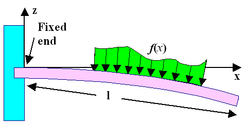
In the first figure employed
for this topic, a point force and a force distribution resulting from putting some brick on the beam, was shown. If you
ponder that figure for a while, you will realize that we only need to consider force distributions in what follows because
they contain point forces as a special case. To make the whole thing completely general, we allow arbitrary force distributions
f(x) as shown here: |
| | |
|
|
|
 | | Some distributed forces acting on a beam
|
|
| |
| |
|
 |
What can we say about the force distribution f(x) in the
drawing? You could produce it by putting down a brick extending from x1 to x2
that has a height profile as given by f(x). We know that the total
force it exerts is simply given by its weight (expressed in Newtons), and that implies that |
| |
| |
| |
| Fto |
= |
x ' = x2
ó
õ
x ' = x1 |
f(x') · dx' |
or |
f(x) | = |
dF(x)
dx |
|
|
| |
| |
|
 |
The left-hand equation with the integral is clear (I hope). The right-hand equation just reverses
the situation. The force distribution
f(x) thus is simply the derivative of the total force you find as you go along the beam in x-direction. |
 |
How about the torque T(x) that some force distribution f(x)
produces at the point x? |
|
 |
Tricky question. I won't go through the derivation but just
give you the rather simple result: |
| | |
|
| |
| T(x) | = |
x
ó
õ
0 | F(x') · dx' |
or |
dT(x)
dx | = |
F(x) | or
| d2T(x)
dx2 |
= f(x) |
|
|
| |
| |
 |
We have what we need. We know what kind of torque is produced by external force
distributions (and also point forces), and from our old equation we know how that relates
to the local radius of curvature. The question now is how the local radius of curvature r relates to the deflection
curve that we want to calculate. |
| |
| |
| |
Radius of Curvature and Differential Equation for the
Deflection Curve |
 |
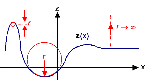
A rather fundamental insight from basic calculus is that any
curve y(x) can be assigned a local radius of curvature r(x) at any point x.
|
|
 |
The figure below indicates schematically how one can "snugly" match
some circle to any portion of the curve and thus assign a radius of curvature, including very small and large values, at
any point. |
| |
| |
| |
 |
| Defining the radius of curvature for arbitrary curves |
|
| |
| |
|
 |
Since the local radius of curvature
r(x) is a well-defined property of the curve itself, the equation giving the curve should also allow
to calculate r(x). In other words: if you can draw it, you must be able to calculate it. As it turns
out, you can calculate it - but the resulting equation, on first sight, is not all that simple. Calculus gives us |
| |
| |
| |
1
r(x) |
= |
z''
(1 + z'2)3/2 |
|
|
| |
| |
|
 |
with z' and z'' denoting, as usual,
the first and second derivatives of the function z(x) |
 |
Mercifully, it's not as bad as it looks. In regions where y(x) is
about parallel to the x-axis (as our beam line), a large radius of curvature always
goes with a very small first derivative; see the figure above, Since we only bend gently,
radii of curvature are going to be large, and we can simply assume that the first derivative of the deflection line is close
enough to zero so we can ignore it.
This gives us1)
1/r(x) »
z'' or, using our fundamental equation for the radius of curvature |
| |
| |
| |
1
r(x) |
= |
z''(x) = |
T(x)
IA(x) · Y |
|
|
| |
| |
|
 |
Bingo! We have a second-order differential equation for z(x), the deflection
curve, that relates the second derivative of that function (that we are after, remember!) to some other functions of x.
I have even allowed the area moment of inertia IA to be now a function of x, meaning
that our beam may now change its cross-section along its length. |
 |
We can even do better than this (or worse, depending on your point of view concerning
differential equations). We know from right above that the torque T(x) is
just the second derivative of the force distribution f(x). Rewriting slightly and differentiating inside
our differential equation above twice more gives us |
| | |
|
|
|
| T''(x) |
= f(x)
= | d2
dx2 |
(YIA(x) · z''(x)) = | Y
IA · z''''(x) |
| | | |
|
for IA = const. |
|
|
| |
| |
|
 |
Bingo once more! The red part is the famous beam bending
equation. It is a differential equation of fourth order, no less!
Mercifully,
it is easy to solve - provided that the cross-section and thus IA is constant and f(x)
is a simple function
If that is not the case things can get (mathematically) rather messy. A real beam has no problem
whatsoever to find the solution. It just bends to the right shape. |
 |
All that remains to do is to solve this equation for some interesting (and very
simple) cases. |
|
 |
If you know anything at all about differential equations, you know that for a fourth-order
differential equation four integration constants will turn up that need to be determined
from independent information.
The independent information that we need for specific
solutions of a beam bending problem are (of course) the boundary conditions.
Let's
look at a few examples to see how this works. |
| | |
|
| |
Bending Beams with Boundary Conditions |
 |
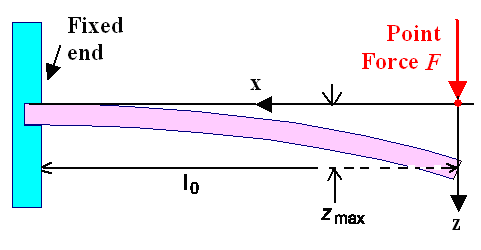
Let's start by calculating the deflection line for a simple version of the the
simple case used for illustrating the beam-bending problem. It is also of relevance for bending a sword. |
| |
|
|
|
 | | First example for calculating a deflection line |
The coordinate system has been adjusted to make the results easy
(e.g. no minus signs). |
|
| |
| |
|
 |
Since we know for this simple case that the torque T is F
· x, we can start directly from the more simple second-order differential equation.
This is good because we (me included) do not know off-hand how to work with force distributions that are not distributed
but "pointy" and thus would need delta-functions or other stuff from rather advanced math that we don't to want
to bother with here.
The decisive differential equation thus is |
| | |
|
|
|
|
| |
| |
 |
Everybody knows what to do now, of course. Just integrate twice, and you have |
| |
| |
| |
| IAY · z''(x) |
= | |
| |
F · x | | |
| |
| |
|
| IAY · z'(x) |
= |
ó
õ
|
F · x · dx |
= |
½F · x2 + C1 |
| | |
| |
| |
| IAY · z(x) |
= |
ó
õ
|
(½F · x2 + C1)dx |
= |
(1/6)F · x3 + C1· x + C2 |
|
|
| |
| |
|
 |
C1 and C1 are the integration constants
that we need to determine from the (sensible!!) boundary conditions. So what are the
boundary conditions? Well, I already gave those
to you, but here we go again: - z(x = l0) = 0
- dz(x = l0) / dz = 0
In words: There is no deflection at the place where the beam is fixed (x = I0)
for the coordinate system here and the slope of the bending line (= dz / dx) at the point is zero.
Inserting that into the general solution above yields |
| | |
|
|
|
| IAY · z'(l0) = 0 |
= |
½F · l02 + C1 |
Þ |
C1 = –½Fl02 |
| | |
| |
|
| IAY · z(l0) = 0 |
= |
(1/6) · l03
– ½Fl2 · l0
+ C2 |
Þ |
C2 = 1/3Fl03 |
|
|
| |
| |
|
 |
Now you see what distinguishes "sensible" boundary conditions from not-so-sensible
ones. We need two and only two boundary conditions to determine the integration constants. The real problem may not always
give you that. Then you are stuck with a large and ugly can of worms that we simply won't open here. |
 |
Now let's celebrate the grand total for our first calculated bending line z(x): |
| |
| |
| |
| z(x) = |
1
IAY |
æ
ç
è
|
(1/6) F · x3 – ½Fl02
· x + (1/3)Fl03 |
ö
÷
ø |
|
|
| |
| |
|
 |
You are entitled to some exclamation now (Something between: "Oh my God" and "F....
off"; but stopping short of: "Let's kill him"). Remember what I said somewhere in the
beginning? (No, it wasn't "let there be light", but thanks anyway). |
 |
Before I make things worse and go for the more complicated stuff, lets look at
one major piece of enlightenment we can get from that result.
It is obvious from the geometry and
from the equation that the maximum deflection is right a x
= 0 or at the tip of your sword = beam. But only from the equation do we get the precise amount: |
| |
| |
| | |
| zmax(x = 0) = |
F · l03
3 Y · IA |
= |
4 F · l03
Y · b · d3 |
|
for a rectangular
beam with width b
and thickness d |
|
|
| |
| |
|
 |
Since Young's modulus
Y is the same for all kinds of steel and iron, differences in how much you can "bend" a sword applying
the same force depend only on:
- The third power of the length l03. Double the length and you deflect 8 times more.
- The areal moment of inertia. Look at this table and you see that making
your sword half as thick (but twice as broad to keep the weight constant) will give you about 4 times more "flex".
- Changing the cross-section and thus the areal moment of inertia IA as you go down the blade.
This is not contained in the equation above but you can appreciate that it could have big effects.
|
| |
| |
| |
Looking at Distributed Loads |
 |
For the grand finale let's look at some simple cases with a distributed
load. A simple distributed load, being constant all over the beam for case as shown below. |
| |
|
|
|
 | Bending the same beam with the same distributed load
but different boundary conditions |
|
| |
| |
|
 |
Let's go straigth to the differential equation and its solution: |
| |
| |
| |
|
| YIA · z''''(x) |
= | | |
f0 | | |
| | |
|
| YIA · z'''(x) |
= | F |
= |
f0 · x + C1 |
| | |
| |
| YIA · z''(x) |
= | T |
= |
½f0 · x2 + C1· x + C2 |
| | | |
| |
| YIA · z'(x) |
= | | |
(1/6)f0 · x3 + ½C1· x2
+ C2· x + C3 | | |
| | |
|
| YIA · z(x) |
= | | |
(1/24)f0 · x4 + (1/6)C1· x3
+ ½C2 · x2 + C3 · x + C4 |
|
|
| |
|
 |
Oh, the magic of differential equations! We have solved all
problems involving a constant distributed load! But don't get excited about how eays
it was! For some more complex function f0 it would be far harder.
Anyway, all that remains
to do now is to determine the four C's, the integration constants. So let's look at the boundary conditions
for the three cases given above. |
|
| |
| | |
| First case |
| z(0) = 0 | |
C4 = 0 |
| z'(0) = 0 | |
C3 = 0 |
| F(l0) = 0 |
|
C1 = – l0 · f0 |
| T(l0) = 0 |
|
C2 = ½l02 · f0 |
|
|
| |
| |
|
 |
This need some explaining, The first two conditions are exactly the ones we already considered for the point load. They haven't changed. But we need two more boundary conditions to
determine four integration constants. So we look at the boundary at right, the end of the beam. What is going on there?
The answer is: nothing! There is no force or momentum, but hey, that's a condition, too. We obviously have F(l)
= T(l) = 0. Both parameters correspond to integrating the distributed force once or twice, respectively,
so we have no problem in using those "zero" conditions |
|
 |
The elastic line z(x) and the maximum deflection z(l) now comes out to
|
| |
| |
| | |
| z(x) = |
f0 · 14
24IAY |
æ
ç
è
| æ
è |
x
1 |
ö4
ø |
– 4 · |
æ
è |
x
1 |
ö3
ø |
+ 6 · |
æ
è |
x
1 |
ö2
ø |
ö
÷
ø |
| | |
| |
| |
| |
| |
| |
| |
| | z(l) = |
f0 · 14
8IAY | |
| |
| |
| |
| |
| |
| |
|
|
| |
| |
|
 |
If we compare that to the case of the point force, we just take f0 ·
1 = F, the single force at the tip of the sword, and see that the ratio of maximum bending is 8/3;
deflection due to a single force is 2.66 times more pronounced than for a comparable distributed force. |
 |
Let's look at the two remaining cases. The boundary conditions and the C's determined
from them are |
| | |
|
|
|
| T(0) = 0 |
| C2 = 0 |
| z'(0) = 0 |
|
C3 = 0 |
| T(l) = 0 |
|
C1 = –½l0 · f |
|
z(0) = 0 |
|
C4 = 0 |
| z(0) = 0 |
| C4 = 0 |
|
T(l0) = 0 |
ö
÷
ø
|
æ
ç
è
| C1 = 5/8l0 · f |
| z(l) = 0 |
|
C3 = 1/24l0 · fl3 |
|
z(l0) = 0 |
C2 = 1/8l02 · f |
|
|
| | |
|
|
 |
I refrain from writing down the final equations for the bending lines; the figure
shows what they will look like quite nicely.
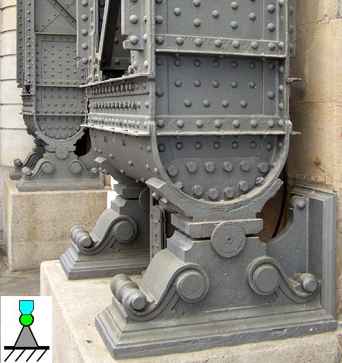
What those boundary conditions mean is graphically clear from the figure, how they are expressed in equations from the table above. What the one on the left in the second
case looks like in reality (for a perpendicular beam is shown in this picture: |
| | |
|
|
|
 |
| Beams carrying the large cupola of the Dresden main station |
| The location is fixed but the torque will be zero since the beam can rotate "freely".
If it couldn't, boundary conditions would no longer be "sensible" and large stresses could occur in the support. |
|
| | |
|
 |
What we have learned is that beam bending is not all that easy, even for the most
simple problems and by using all kinds of approximations and tricks.
The bending of a real sword that has a cross-section
that changes along its lengths, and for conditions where we bend a lot (e.g. the famous semi-circle around the smith) calculation
would be difficult and only feasible numerically with a powerful computer. |
|
 |
So next time you see the steel skeleton of some skyscraper or any other mechanical
constructions (like airplanes or cars) you realize that all you see are a lot of beams with different lengths and areal
moments of inertia, hooked up in some way that defines the boundary conditions.
Rest assured that somebody has calculated
the bending (and all the other deformations that might occur) of all those beams under the load they are going to bear,
and has made sure that all the deflections stay within allowed limits. If they wouldn't,
beams would be made stronger or more beams would be added. Of course, you can build a momentous pyramid or Gothic cathedral
with doing any calculations of that sort. Just make sure that all load bearing parts are far larger than really needed.
How large that is you find out by looking at pyramids or cathedrals that collapsed during their erection or shortly after
(so they are no longer with us.) Use trial and error in other words. What you will not
get in this way, however, are airplanes that actually fly because they would be too heavy.
Modern structural "beam-based"
constructs are fully calculated, starting with the beam bending theory given here (and going far, far, beyond). That allows
to make beams as light-weight as possible without compromising structural integrity. The fact that structural collapse essentially
never happens anymore tells you that even super-complicated bending calculations can be done with precision. But only because
nowadays we have the computer power needed to do that. |
| |
| |
| | |
|
| | |
|
1) I do know that there should be a minus sign but I omit it since it is not important.
Other quantities that I used before also should have had a minus sign. In the end, choosing proper axes' orientations (z-axis
downward, for example), everything comes without minus signs as written here |
| | |
|
© H. Föll (Iron, Steel and Swords script)


