12.2 Static Sword Properties
12.2.1 Sword Bending: Purely Elastic
Assessing static sword properties means to try to change the shape of the sword by using forces acting on it. You could, for instance, try to make it longer by pulling at it. That sounds a bit weird but that is how we assessed basic static properties of materials in chapter 3. Remember the tensile test? That gave us Young's modulus, among other things. Doing a tensile test in reverse - pushing instead of pulling - was also mentioned and we will deal with that in the next sub-chapter.
In other words: we go for the classical "bending beam" situation. That was already discussed by Leonardo da Vinci and Galileo Galilei - but it is still the night mare of fledgling engineering students.
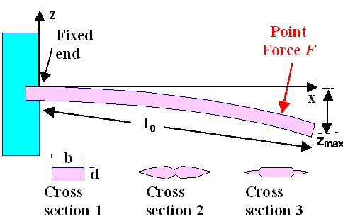
How you could do the experiment with an actual sword I have shown you before. Below is therefore a picture showing only the abstract essentials needed for an in-depth analys
 |
|
| Basic "bending beam" experiment. The cross-section can have any shape |
Measuring that number is not too difficult. But calculating that number is a daunting task. "Beam bending" is the first thing that all students have to master who are forced to attend "Technical Mechanics" lectures, and it will have been an unforgettable experience to the surviving physicists and engineers. You not only had to understand something called "area moment of inertia", you actually had to understand and be able to solve a fourth-order differential equation, requiring proficiency in differentiation and integration and a fearless mind. The links, by the way, lead you to the science modules dealing with the topic in question without avoiding equations.
This is bad news already but it will get worse! It is tough to calculate the bending of a beam with a constant cross-section but you just about can forget it completely for a variable cross-section, like for your sword. For a computer it is no problem at all, but if you try to do it with pencil and paper only, you will run into your limits rather quickly.
- Guess: Double the force F and you will double zmax?
Reality: Correct as long as zF is much smaller than the length l0 of your blade and the force is not too large. - Guess: Double the length, and the deflection zmax will double?
Reality: Completely wrong! The deflection increases with the third power of the length! Double the length and it will be 8-fold, half it and it will be 1/8! That's why your sword will wiggle a lot more if you make it just somewhat longer. - Guess: "Stiff" materials - those with a large Young's modulus Y - will bend less than resilient
materials. So the guess is that zmax goes inversely with Y?
Reality: Correct - that is what happens. Increase Y by a factor of 2 and the deflection zmax will be halfed. - Guess: A thin blade bends more than a thick one. So zmax goes inversely with the thickness
d? Doubling the thickness leads to ½ of the deflection?
Reality: Completely wrong again! The deflection goes with the inverse of the third power of the thickness! Double the thickness and the deflection will be 1 / 8 of the old value. - Guess: A wide blade bends less than a narrow blade. So the deflection goes inversely with the width b
of the blade?
Reality: Yes - that's correct.
The deflection increases
|
What we got so far is tricky enough - and we have not yet considered that the cross-section (and therefore the area momentum) typically changes as we go along the length of a blade. Not to mention that for curved blades we no longer have a "simple" one-dimensional problem. How do we deal with that?
If your blade is curved, it will usually not bend very much anyway since it is not very thin at any place. There is no curved equivalent of the small sword shown in the bending picture. Otherwise - see above.