 |
There is more to the iron-carbon phase diagram than related in the backbone. In
particular, there is some nomenclature that I avoided in the main text but that is important for understanding other writings
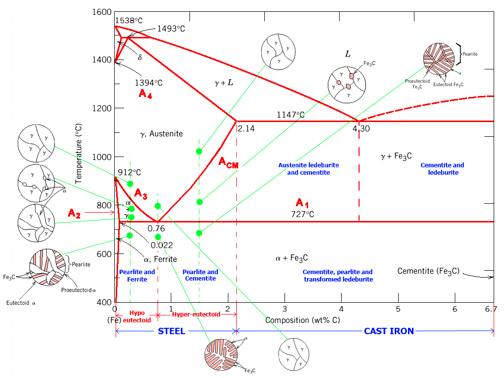
about iron and steel. So let's start with a phase diagram that contains maximal information: |
| |
|
|
|
 | | Iron-carbon Phase Diagram |
| Source: Arabic Internet site |
|
| | |
|
|
 |
The important boundaries (the lines) separating phases have
some universally used abbreviations:
- A 1: The upper limit of the ferrite / cementite phase field (horizontal
line going through the eutectoid point).
- A2: The temperature where iron looses its magnetism (so-called Curie
temperature). Note that for pure iron this is still in the a-phase.
- A3
: The boundary between the g austenite and the austenite/ ferrite field.
- A4: The point in this case where a changes
to d at high temperatures.
- ACM: The boundary between the g austenite
and the austenite / cementite field.
|
|
|
Why would anybody abbreviate a temperature with the letter "A"? Well,
it stands for "arrest", something that happens in the slope of dilatometric
or thermal curves recorded whenever phase diagrams where first measured.
Statements like "the addition of
x lowers A3" are now clear. |
|
 |
The circular insets give a schematic idea of what the structure would like at
the compositions and temperatures indicated. |
 |
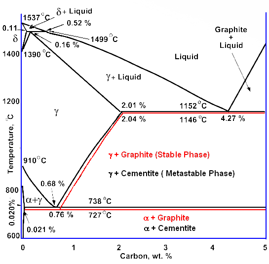
The next thing to know is that the phase diagrams above is actually
not the true iron-carbon phase diagram. I lied to you.
Some mixture of cementite and iron is not the configuration
that allows the system to achieve total nirvana. That would be a iron - graphite mixture. |
|
 |
All the cementite forming is just a transient phase on the way to nirvana; it will decay into pure carbon
(graphite) and iron in due time. Due time, however, means millennia and more at room
temperature for plain carbon steel. Cementite, in other words, is a very long-lived metastable phase under normal conditions. It thus makes sense to use it for something that is not
a true phase diagram for purists, but that sane normal folks will call "phase diagram" anyway.
We are also
justified in doing this because the "real" iron - graphite phase diagram looks almost exactly like the iron -
cementite "phase diagram". Here is the proof: |
| |
| |
| |
 |
Iron - carbon phase diagram in comparison to
the iron cementite phase diagram |
|
| | |
|
 |
Does that mean that we don't have to worry about graphite being formed? Yes and
no. Like almost always, it depends: |
|
 |
For plain carbon steel with carbon concentrations
below 2 %, you needn't worry, indeed. Graphite is never formed and the usual phase diagram
covers everything nicely.
For cast-iron
, with carbon concentrations up to a few percent you need to worry. Graphite might form, depending on conditions.
For alloy steel, the usual thing nowadays, you need to worry, too. Some alloying
elements, in particular silicon (Si) but also nickel (Ni), promote graphite formation. |
| | |
|
© H. Föll (Iron, Steel and Swords script)

