|
11.5 Wootz Swords |
| 11.5.1 The Winner is....
|
| |
What It's All About |
 |
Wootz swords in my terminology are swords that
were - made from crucible steel, and
- show a nice
"water" pattern on the blade.
The great Verhoeven - Wadsworth Jousting Tournament was
all about how to make wootz blades. So who won the tournament? Before I tell you, I need to ask if you remember what, exactly,
the contestants fought for? I thought so. One tends to forget what was so important to merit a life-and-death fight if one
doesn't watch all the time. Why, exactly, did the Church burn Giordano Bruno some time ago? Which church?
So let's recall what it is all about. The
short version is here. |
| |
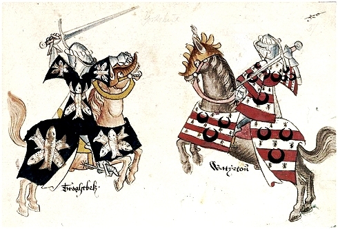 |
| Still at it. |
| Source: Sir Thomas Holme's Book of Arms; ca. 1440 |
|
 |
The big question was (and is): |
| | |
What does it take to produce a nice
wootz pattern on a piece of steel like a sword.
|
|
| |
 |
The way I put it the emphasize is on "nice", and that is not a good
scientific word because it is hard to attach a number measuring the degree of nicety. It is just as hard to define what
separates a nice wootz pattern from a run-of-the-mill one, as it is to define what separates
pornography from art. Yet you just know it when you see it.
Below are nice wootz patterns; here
are a few more |
|
|
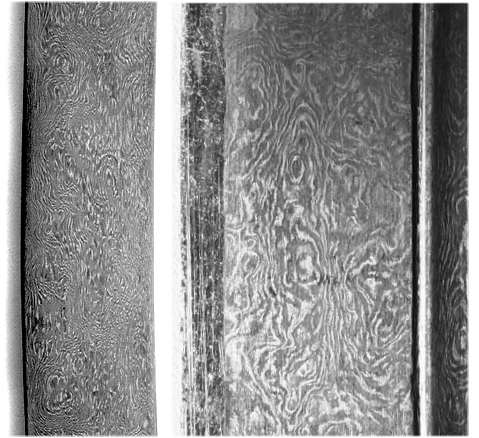 |
Nice wootz patterns
Note: The cementite-rich regions are white here |
| Source: Commercials for not-so-old wootz swords (18th century or younger) you could
buy from antique dealers in 2014 |
|
|
 |
You only see the pattern after the (polished) blade has been properly etched.
True connoisseurs have with little success tried to classify "nice" in more detail; consult the illustration
module if you must know. In essence one distinguishes: - Stripe pattern
- Water pattern
- Wave pattern
- Net pattern
- Wood Grain pattern or Mottled pattern
- Step pattern or Mohammed's ladder (kirk nardeban) with or without "roses".
My own definition of "nice pattern" is simple (and rather useless):
A "nice pattern" is based on a structure that would allow, in principle, to produce a "kirk nardeban"
or rose pattern. | |
|
 |
In the crucible steel
chapter I have given you already a lot of information about wootz steel; now is a good time to refresh your memory.
Having you back, I propose that you now make a wootz sword with a nice pattern.
You started out as a smith already in chapter
2, after all. By now you are a smith in chapter 11 and you have learnt a lot about iron and steel in the meantime. Let's
see if all that knowledge allows you to do the job. It shouldn't be all that difficult because several modern smiths are at it right now - and some have succeeded. I'm going to help a bit,
though.
Le's start by working our way back and see if we can figure out what it takes to make a wootz sword. Generating
the process recipe will also bring out the still open questions and allow us to focus on what, exactly, all the jousting
is about.
So what do we know "for sure" about the making of wootz swords? |
|
 |
First of all we do know what causes the pattern, the interlaced
dark and bright regions on the blade. The "color" reflects the difference in the cementite concentration or, being
a bit more precise, the difference in the concentration of largish cementite precipitates.
You must etch your blade a bit to make this difference visible but this is a relatively trivial (if sometimes frustrating)
part of the recipe and we will not discus the various techniques for that.
Looking at the blades above with a microscope
at medium magnification (around 100x) will give pictures like these: |
| | |
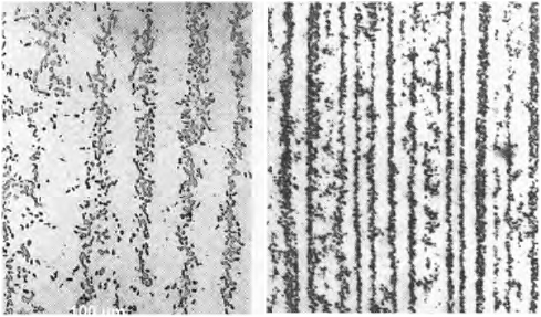 |
Black cementite particles in a (pearlite?) matrix
Note: The cementite is black here.
|
| Source Verhoeven 2002
|
|
 |
So let's ask a simple first question. We know that one needs high-carbon steel
for wootz patterns. So just how much carbon do we need to form sufficient
cementite for forming the pattern?
Let's start by considering how much cementite is actually there "to see"
in a steel sample with, to make it easy, 1 wt % carbon. A simple question but the answer needs a bit of thought. |
| | |
|
| |
From Carbon to Cementite |
 |
In order to keep things simple we envision a 100 g (or 100 pound or 100 ton)
cube of carbon steel. If 1 % of the weight comes
from the carbon in there, we have 99 grams of iron and 1 gram of carbon, obviously.
The carbon will eventually turn
into cementite, Fe3C. Any carbon atom thus takes three iron atoms away, and that means you have less iron
now. I know it is a bit confusing because you still have the same number of iron atoms
in the cube. But an iron atom contained in cementite is not
part of an iron crystal (ferrite at room temperature) anymore, just as an oxygen atom
in a water molecule is not part of the air anymore.
Now to the big question: How much room
does the cementite occupy in our cube? And what could we "see" by looking at the cube? Simple questions but the
answers take quite a bit of thought.
We need to keep track of atom counts now and in order to do that we first need
to go to atomic concentrations. I gave you a whole
module dealing with that, and you can look up there how it is done. Or just believe me:
1 wt% of carbon corresponds to 4.81 at% of carbon.
That means that from all the atoms in our 100 grams of steel
4.81 % are carbon atoms, and 95.19 % are iron atoms. |
|
 |
Now imagine a smaller cube containing 9.519 iron atoms and and 481 carbon atoms
and you get the right relation. Altogether we have 9.519 + 481=10.000 atoms (surprise?).
Now we form cementite. Our
481 carbon atoms will need 3 × 481=1443 iron atoms to form one molecule of cementite, Fe3C. That
means we have only 9.519 - 1443=8.076 iron atoms left for being iron. Relative to the 10.000 atoms we started with this
equals 80.76 at% and the rest, 19.24 % of all the atoms in the cube, are now in the cementite! That's what
just 1 wt % of carbon will do! With 6.7 wt% carbon only cementite would be left
I'll illustrate that with a very simple picture:4) |
| |
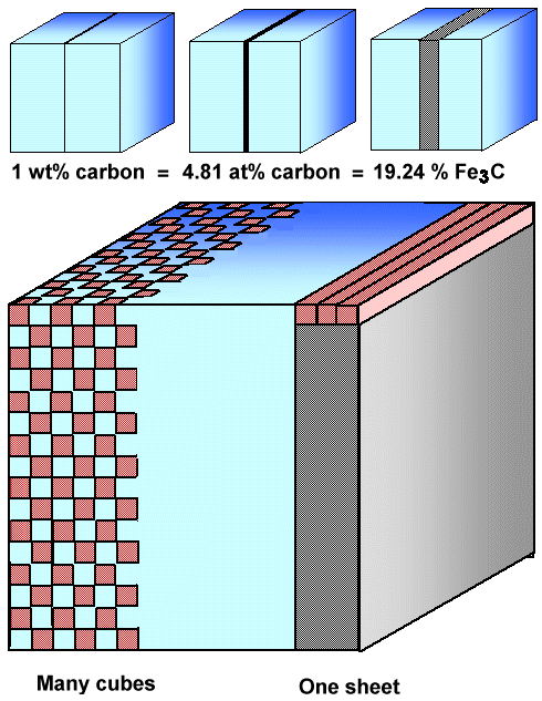 |
| Visualizing percentages in concentrations |
|
| |
 |
The small blue cubes in the upper part of the picture just visualize the percentages.
The big cube demonstrates what you could get by breaking up the solid block of cementite. First look a the right hand side.
The grey part corresponds to the volume the cementite takes up if it would be in one block. Now consider that block as being
built up by rods, e.g. three abreast as shown on top. Now break one rod into cubes and just leave every other cube in place.
Than you can pack six rows of interrupted cubes into your crystal replacing the three
full rods shown. Continue on the next level and you have the structure on the left-hand side of the big cube above. |
 |
What seems to become clear is that you can make a lot
of rather big cementite particles this way, or a hell of a lot of smaller ones - from
just 1 wt% of carbon! With some special arrangement of all these precipitates you should be able to produce a pattern.
|
| |
Too bad that this is wrong!
|
|
|
 |
You don't see it? Then look at the phase
diagram. Or just believe me when I remind you that with the first 0.76 wt% of carbon you simply form pearlite. A cube of just 0,76 wt% steel would simply consist
of pearlite grains, i.e. grains "filled" with the by now well-known "zebra"
structure. Of course, part of the "zebra" are the cementite lamellae but everything is so small (around or
below the 1 µm region) that you simply cannot see any pattern on a pearlite surface,
not to mention a "nice" one. The cementite in the pearlite is effectively invisible to us and the only optical
effect is the "pearl-like luster". |
 |
In our 1 wt% example we have only 0.24 wt% carbon left to form some extra cementite
but that might not be enough for forming visible cementite.
For the formation of
a nice wootz pattern we need cementite in excess
of the one in the pearlite, and this means that we need to go well above the eutectoid 0.76 wt% carbon concentration. So
let's take 1.76 wt% and we are right back to the picture above (with the "blue" in the cube now denoting
pearlite).
Incidentally, that's a typical carbon concentration for crucible steel and wootz swords. |
| |
|
| |
Getting High Carbon Steel |
 |
Now we know what we need: a sufficient amount of about 2 wt% carbon steel, i.e.
ultra-high carbon steel (UHCS). Where should you look for that before 1800 or so? It's a tough assignment - even for the
time traveler who knows all about steel. For an ancient European smith it was almost impossible to get UHCS. If you followed
me you know by now that all the bloomeries of old did not just produce wrought iron but all kinds of carbon (and phosphorous)
steel, up to and including cast iron. However, 2 wt% of carbon is difficult to make in a bloomery. It is too much carbon
for a regular solid state bloomery process (look at this
picture to refresh your memory). If you would try to smelt 2 % C UHCS in a bloomery, you would quite likely run into
the other extreme and end up with cast iron, getting carbon
concentrations that are too large. |
|
 |
Europeans thus couldn't easily have forged wootz swords - they lacked the raw
material. |
 |
Smart Indians or Iranians, on the other hand, employed a crucible process after
smelting raw iron / steel in a bloomery and made UHCS conscientiously. No, they did
not! They did not produce steel with about 2 wt% carbon intentionally, they produced
it by default. They would for sure have preferred to make 0.7 wt% steel but couldn't because their process was temperature limited.
If everything worked, the resulting wootz or bulat
cake was liquid once with a bit of liquid slag on top. Cooling down solidified the steel without incorporating the slag.
This made crucible steel superior to bloomery steel with respect to slag inclusions. |
|
 |
Of course, crucible steel was not pure high-carbon steel
and it was not always "perfect" either. It contained the usual impurities, e.g. phosphorous, depending on what
was contained in the ingredients. There seems to be some evidence that the stuff wasn't always completely molten either,
just what one would suspect. The resulting cake then was rather inhomogeneous. |
 |
But let's go on. Let's assume that you, the ancient smith, did get into possession
of a good wootz cake with the required 2 wt% carbon or so, and not too much dirt and other problems. What's
next? |
| |
| |
| |
Shaping the Cementite |
 |
You now have a 2 wt% carbon steel that will produce sufficient cementite for pattern
formation. But you, like all of us, know that during cooling the cementite forming first (the "primary
cementite") will tend to line the grain boundaries,
and that the resulting steel is completely brittle and thus almost useless for swords
- but not for many other things like punches or dies for wire
drawing. I'm saying "almost" useless since the famed Ulfberht swords, if indeed made from crucible steel,
would fall into that category. Why they might have been perceived as very good is not so clear; I have already made some comments to that.
Somebody, sometime (maybe around 500 AD) and somewhere (in India or
thereabouts) ran across the first major trick that needs to be employed to avoid this: |
| |
|
Ball up (spheroidize) your cementite!
|
|
|
 |
Produce little "spheres" or just pebble-like particles or precipitates instead of
shells around grains, long needles (look up "Widmanstätten")
or anything spreading in some direction. The process for doing this is called "spheroidization".
|
 |
I already gave you a list of how that can be done. Read up on it; here I only emphasize the major points:
- Since we do not want cementite at the grain boundaries, it is essential to nucleate the stuff inside the grains. Having
very strong carbide-forming elements
like (Nb), titanium (Ti) and vanadium (V) around is certainly helpful or even necessary. Metal carbides will form first
and then act as nuclei for cementite precipitation.
- Banging with a hammer or just deforming heavily helps because it mechanically breaks up large cementite particles, making
it easier to form many "spheres" out of one large sheet or needle.
- Cycling at temperatures around the A1 temperature
of 727 oC (1341 oF) helps. If done right it will coarsen the cementite particle and sharpen the distribution;
see below. The smith does both when he forges a blade. Heat it up, bang it, cooling, stop. Heat it up, .... A tricky smith
might even use more heats then necessary to make many cycles.
|
| |
 |
Whatever you did to get your cementite to ball up - after that has happened the second major
trick comes into play: |
|
|
Forge at low temperatures!
|
|
| |
|
You must never ever again raise the temperature to well
above the A1 temperature of 727 oC (1341
oF) where ferrite changes to austenite! If you do, a lot of the spheroidized cementite will dissolve and chances
are that it precipitates in unwanted shapes during cooling. A little bit above A1 for a short time - OK.
But never a lot above A1 or for long times! |
| |
This goes against all normal
principles of forging!
|
|
 |
The smith just must be acutely aware of all of that. An ancient European smith
who by accident got hold of some crucible steel was not likely to find that out by playing around a bit with the stuff.
Western 18th and 19th century smiths indeed didn't get it according to some sources.
Since this is not something you
find out yourself, getting in possession of some crucible steel just couldn't do much good in the "West".
In contrast, the ancient smiths in India and Persia knew what to do 1600 years or so ago. They did make blades from crucible
UHCS that contain spheroidized cementite and are no longer brittle. The
link shows what that looks like.
Did you believe that? You sucker! The link shows what modern
scientists ( O. D. Sherby and J. Wadsworth, actually) can do with modern methods and knowledge. The theory, though a bit
involved, is also well-known by now 1), not to mention that times, temperatures
and impurity content are known and controlled.
The question is: Did the really old smiths working with crucible steel
produce spheroidized cementite? |
|
 |
I have yet to see a micrograph of old crucible steel
that shows spheroidized cementite. In contrast, I (and you) have seen structures that show what we want to avoid: grain
boundaries solidly encased in cementite. Just look at the picture of the "Stuttgart"
Ulfberht sword that as been made from crucible steel according to Alan Williams.
"But what about the pictures up there", you might say. "Don't they
show spheroidized cementite in bands?" Yes, they do. But these pictures are from much later wootz blades with
a pattern and we aren't there yet. Moreover, the steel has been etched in a way to bring out the wootz pattern and not to show the structure. You just do not know in these cases what you do not
see because of the undefined etching. |
 |
What we would need to see at this stage are metallographic examinations of crucible
steel blades that do not show a water pattern. Alan Williams in his book about Ulfberht
swords supplies quite a few pictures of that - and not one of these pictures shows good spheroidization!
There are certainly
more metallographic investigations into the structure of old crucible steel, and I do not know them all. From what I know I show you one example:
|
| |
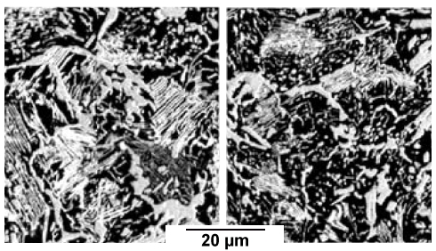 | | Phosphorous-lean area |
Phosphorous-rich area |
| Cementite (white) in (forged) crucible steel |
| Source: M. R. Barnett et al. 2) |
|
 |
The sample origin is a bit unclear. It's probably 19th or 18th century, it is
certainly not ancient. We see several remarkable things:
- There is good spheroidization - but only in parts of the sample that contains an appreciable phosphorus concentration.
This illustrates that nucleation and thus trace impurities might play a major role in crucible steel processing.
- The crucible steel people obviously did have a phosphorous problem like everybody else; at least on occasion.
- The phosphorous is inhomogeneously distributed. There are obviously limits to uniformity even in formerly liquid steel.
|
|
 |
At this point we simply learn that not all crucible steel swords are born
equal. If everything worked and the cementite is nicely spheroidized everywhere, these blades were very hard throughout
but not brittle. But rather brittle blades must have been made, too, as well as blades given to cold shortness, inhomogeneous
blades and whatever else results if not everything is "just right" in the production of the blade.
The picture
below shows a small section of an otherwise magnificent wootz tulwar where the pattern is not present in parts: |
| |
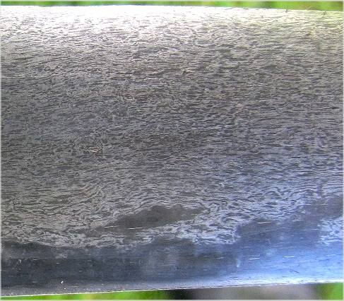 | | "Defective" area in a wootz tulwar |
| Source. Tulwar restored and photographed by me |
|
|
 |
Did something go wrong during the forging of this wootz blade? Well, yes - but in a peculiar
way: |
| |
|
Surprise!
This blade is actually "faked wootz"
|
|
|
| |
 |
As I learned just recently (fall 2017), this blade has a core of regular non-wootz steel with
a thin layer of wootz steel laminated to both sides. In the "defective" area, this thin wootz layer has been polished
off. More to that in the link given above. |
 |
Now let's assume that you managed to forge a blade that contains nicely spheroidized
cementite. Now we come to the key question: |
| | |
Would your blade show a pattern?
If it does, would it be a nice pattern?
|
|
|
 |
A pattern or no pattern? This is the question. Then we have follow-up questions:
- Could a pattern result without you, the smith, being aware of that?
- If a pattern does result: could you have prevented it?
- If a pattern does not result: is there anything that you, the smith could do to generate one?
- If a pattern does result but it isn't "nice": is there anything you can do to change that?
In the link you find a lively discussion among real smiths where
some of these questions are addressed. In what follows I will spend quite some time on this topic, so be patient. |
| |
| |
| |
Forming a Pattern You Can See - Some Basics |
 |
We want to make a nice clearly visible pattern. The first question in this context
is: What can you see and what is invisible? Not an easy question. With proper light, you can see a single hair. A hair is
about 30 µm (=0.03 mm) thick but pretty long. Could you see a 30 µm diameter cementite sphere, cut in half and
embedded in featureless "polished" iron? (Left hand picture below). Probably just so, as a tiny speck under certain
good illumination condition. Illumination is important; at night you can't see all that much after all. So let's assume
that you have always the best illumination to keep the subject simple. |
|
 |
Could you see a lot of (cut in
half) 30 µm or so cementite spheres that are uniformly distributed in a (polished) iron matrix? (Middle picture below)
No, you can't. You cannot "see" all the individual particles. A polished sample after etching might look darker
and bit motley compared to a pure iron sample - but that's it.
You only "see" something if the cementite
is distributed in a non-uniform way in some kind of banding (right hand picture below).
Here is my not very good attempt to illustrate all of this in a very schematic way:
|
| |
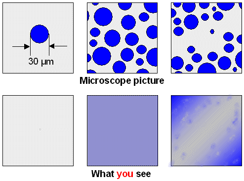 |
| "Seeing" cementite |
|
|
 |
Note that we need at least four parameters to describe the banded
structure in the upper right-hand corner:
- Size distribution of the cementite particles. At the minimum we need the average size and the "standard deviation",
a measure of the spread in sizes.
- Average distance between the particles in a band.
- Average distance between bands.
It is easy to come up with more variables but let's stay simple. Now ask yourself. What is going to happen to the
visibility of the pattern if I change one of those parameters? The extremes are clear. Make the average diameter of the
particles or the distance between bands very small and there goes your visibility. Otherwise it is not so simple, not to
mention that the etching and the lighting also come into play. |
 |
Are there any rules of thumb for those parameters? Yes - all
you need to do is to look at the pictures above or the one right below. They show microscopic cementite particle distributions
that do produce a clear pattern: |
|
|
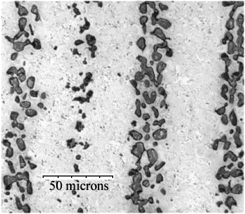 |
| Parameters for visible cementite bands |
| Source: Verhoeven, Pendray 3) |
|
|
 |
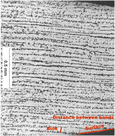
We "see" that a distance between the bands of around 50
µm on the blade is fine, and that particle sizes around 5 µm are fine, too - provided there are a lot! Average
distances between particles in a band should obviously be small, well below 5 µm. In three dimensions we have parallel
sheets or bands of cementite particles,
of course. Since the surface intersects those bands at a small angle, the distance between the bands will be considerably
larger there; look at the picture below or this
module to see that. |
 |
Now we have a good idea of what we need to make: |
| |
|
Sheets (or bands) of cementite particles with the parameters from above that are intersected by the blade
surface.
|
|
|
 |
We knew that all along, of course. But now we know also some numbers - and that
is a very valuable asset. |
 |
We know now, for example, that we need not only to spheroidize our cementite,
we need to do it in a way where we get a high density of particles with a diameter of several µm. If we do that and
distribute these particles uniformly in the blade, we will not
get a visible pattern. If we distribute them in well-defined layers about 50 µm apart, we will be able to produce nice patterns on the blade.
How about something in between? Not a uniform distribution, but
no well-defined layered structure either? That might also produce a pattern - but not necessarily a "nice" one! |
|
 |
We are getting closer to what the fight is all about. Simplified,
the Wadsworth group maintains that it is relatively easy to get patterns with just about any
UHCS steel, including old-fashioned crucible steel, by following a few simple rules: |
| |
- Cool slowly, producing a relatively coarse grain structure and possibly some Widmanstätten
cementite structure.
- Break up the cementite by forging; heavy forging produces finer structures.
- Reheat somewhat, inducing spheroidization.
- Most important: Get close to but never above the transformation temperature A1
This recipe is not all that new. It is actually what Käthe Harnecker
- a woman! - working for the "Zwilling J. A. Henckels" corporation did in 1924! In words: nineteen
twenty four! She made some very good knifes from 1.2 % - 1.5 % carbon steel
that show a clear cementite pattern!
We might not rate it as a "nice" pattern but then we have only bad copies
of the original pictures that do not show details of the structure. It is certainly as good as the
one shown by the Wadsworth group. | |
|
| |
|
 |
Käthe Harnecker and possibly the Wadsworth group, however, did not yet include
another key ingredient into their recipe, the third major trick: Cyclingthe temperature just around the A1 transformation temperature.
This will tend to make the cementite particles larger and the size distribution narrower, and the region in between precipitate
bands more devoid of the stuff. |
| |
|
|
| |
 |
Strangely enough, I have rarely encountered this term in connection with wootz
patterns. Ostwald ripening, sometimes called "particle coarsening", is a process that kills small precipitates
in favor of larger ones. |
|
|
Start with a distribution of a lot of precipitates with all all kinds of diameters, do some
Ostwald ripening, and you are left with fewer precipitates, all of which are large - just as in the picture
above. Originally, there might have been a lot of smaller cementite particles between the bands but after some Ostwald
ripening they all have disappeared. Precipitates below a certain size shrink and the carbon they release goes to the bigger
ones so they grow.
What does it take to inducing Oswald ripening? In the most simple case you just keep your sample
at high temperatures for a while. If you want to be a bit more sophisticated, you use a transition temperature around which
you oscillate the temperature like this: | |
|
| |
|
- Go just above A1, so all precipitates start to dissolve, meaning
they shrink in size. This takes some time. Large precipitates take longer to disappear than smaller ones.
- Keep the time so short that only small precipitates had enough time to disappear completely while the larger ones are
still around, just smaller.
- Cool below A1 so precipitation starts again.
- The not yet dissolved remains of the originally large precipitates now act as nuclei and grow - to a size even larger
than their starting value. The originally very small ones do not reappear.
- Repeat.
- Repeat - until the desired coarsening has been achieved or you run out of beer, whatever comes first.
|
 |
Of course, everything needs to be done "just
right" and there are many ways of doing it wrong. More to that in the links given. What you might get looks schematically
like this: |
|
|
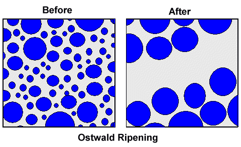 |
| Cementite distribution before and after Ostwald ripening |
|
|
 |
In the microscope picture above you can see that
severe Ostwald ripening was employed. You don't see it? Consider:
- The precipitates in the bands are all rather large.
- There are hardly any small precipitates.
- The second band from the left has few and smaller precipitates than the other three ones. It is also right in the middle
between the two more prominent bands. Add a few more cycles and it will disappear, feeding the precipitates in the bands
to the left and right.
|
 |
Now take some UHCS, employ all of the above, and optimize the many parameters
involved. It might produce produce a wootz pattern; maybe even a reasonably nice one.
So Wadsworth wins? Not yet! Two questions remain:
- While patterns obviously can be obtained from UHCS steel by following rather clear guidelines, we do not really know
why they form! Our guidelines only provide for spheroidization
and narrowing of the size distribution. They do not "somehow" provide for
the required non-uniform cementite precipitate distribution in bands. Think about it!
There is so far no reason whatsoever, why the precipitates should not be distributed homogeneously.
- Even if we "somehow" do get a non-uniform or inhomogeneous cementite precipitate distribution, we do not necessarily
get parallel layers of cementite particles or bands, needed for making some of the fancier
patterns like "kirk nardeban" also known as Mohammed's ladder and therefore for "nice" patterns.
|
| |
 |
Wadsworth and others certainly tried to answer the question implicitly contained
in these two statements. I won't go into that here, however, because it is not convincing. It is more rewarding to invoke
Verhoeven now. Most of his work centers on these two points. So let's see what he has to offer. |
| |
| |
| |
Forming a Pattern You Can See - Some Possibilities |
 |
How do you get cementite precipitates to agglomerate in the right geometry? Sheets
of cementite particles running roughly parallel to the blade surface at sizes and spacings
as discussed above?
There are several possible answers, let me list four of them:
- The process of drawing a compact piece of UHCS (a wootz cake, billet, ingot or whatever
else) into a thin and very long, more or less 2-dimensional object like a sword blade, if done "right" by forging,
milling or whatever, will produce an inhomogeneous precipitate distribution even if it was homogeneous in the starting ingot.
The structure (=cementite distribution) of the starting material could be uniform in this case.
That this works to some
extent was demonstrated by Harnecker, Wadsworth,
Furrer, and meanwhile many
others. However, fancier patterns like "kirk nardeban"
have yet to be made in this way. It might not be possible, however.
- The process of making a compact piece of UHCS (a wootz cake, billet, ingot or whatever
else)" is decisive. You must get the cementite precipitates, or potent nuclei for these precipitates, to agglomerate
with the right geometry already in your ingot: sheets running roughly parallel to the wootz cake surface but at a much larger
spacing than later in the blade.
You need a much larger spacing because you now must forge the blade by drawing out
the cake in such a way as not to disturb the arrangements. Since the blade is much thinner, the sheets of precipitates are
moving much closer to each other. - You need some mix of the two mechanisms described above.
- There are other mechanisms involved.
|
|
 |
Wadsworth and his followers lean to the first possibility; let's call it structure by forging. Verhoeven and his followers champion the second one, which I will call
structure by dendrites for reasons you shall see shortly. |
 |
Now let' s look at some basic possibilities for forming a pattern. Not yet a nice
pattern, just a pattern. |
| |
|
 |
1. Possibility. Starting point:
UHSC with cementite-encapsuled grains and some pearlite inside like in this
picture. The structure is uniform. |
|
 |
All you need to do is to draw out your cake or billet with a hammer or roller.
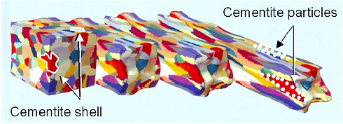
The initially "roundish" grains will deform into a longish structure. The cementite shell cannot deform since
it is brittle. It will break up into small pieces that are still sitting at the grain boundary. Schematically this looks
like this: |
| |
|
 |
Braking up cementite shells by elongation.
This is actually a calculated picture!
|
| Source: Fraunhofer Institut für Werkstoffmechnik; Halle, Germany; Jahresbericht
2013; p. 7. |
|
|
 |
In the picture above I have drawn in schematically
two cementite shells in white, and how they would end up as particles in the elongated structure.
Now polish the surface,
etch and look at it. What you see might look like this: |
| | |
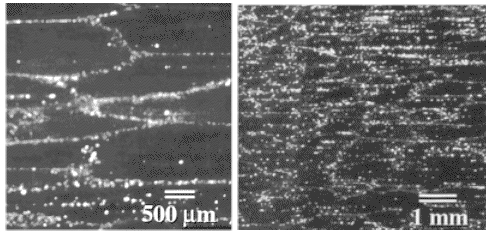 |
| "Grain boundary " wootz |
| Source Taleff; Wadsworth group
|
|
| |
 |
The picture should look familiar; you have seen it before.
Note that I'm not claiming that the real structure shown in these pictures is exactly
what I have described, just that it looks like it. The way it
was made, however, would fit the general idea.
What we have is a certain amount of alignment of cementite particles
just by drawing out the material. A purely geometric effect, in other words. I wouldn't call it a nice
wootz structure, however. |
| |
| |
 |
2. Possibility. Starting point: UHSC with long cementite
needles all over the place, uniform distribution |
|
 |
I'm talking about a structure like this: |
| |
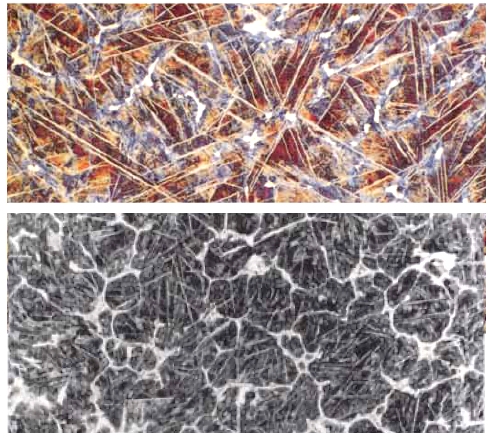 |
Wootz steel with cementite needles
200x, 1 % - 1,2 % carbon, wootz from the Deccan
region,
early historical period (whatever that means) |
| Source: David Scott
|
|
|
 |
On top is supposedly real wootz cake material with predominantly long (white)
cementite needles. The picture at the bottom is from a "prill" stuck to the lid of a crucible; it features needles
and grain boundary cementite. I leave open at the moment how one gets all these needles;
you might also just look up the "Widmannstätten"
module |
 |
Draw out your cake or billet with a hammer or roller once more. The initially
"roundish" grains will deform into a longish structure as before. The cementite needles will break up in shorter
needles and particles. As the grains get elongated, the needle salad will get a preferential orientation into the drawing
direction. A purely geometric effect once more.
.Schematically this looks like this: |
| |
|
 | | Pattern formation by orienting needles |
|
| |
 |
Sorry - I'm not an artist. The red lines just illustrate how the elongation of
the grain aligns the needles that keep their relative position to some extent. Now imagine the situation in three dimensions
with a higher density of needles and needle fragments. Polish the surface, etch and look at it. It might look like this: |
| |
|
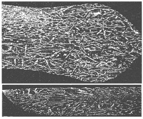 | | Pattern formation by orienting needles? |
|
|
 |
The picture should look familiar once more; you have seen it before. Note that I'm not claiming that the real structure shown in these pictures
is exactly what I have described above. The way it
was made, however, would fit the general idea. |
| | |
|
 |
3. Possibility. Starting point:
UHSC in "cake" shape (for example a wootz cake) with cementite or strong carbide forming elements arranged in
a layered or striated structure as shown: |
| |
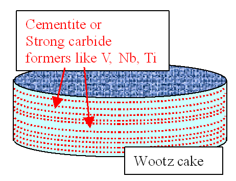 |
| Wootz cake with striated distribution of cementite / carbide formers |
|
| |
 |
If the picture looks slightly familiar - that's because you may have seen in
in chapter 9.
|
 |
You may now wonder how you run a crucible process in such a way hat this kind
of structure evolves. The answer is: I don't know. I have made suggestions but I have no idea what, exactly one needs to do to make it work nor if it ever just
happened or if it is possible at all in UHSC. I do know, however, that this kind of structure is observed in lots of other stuff that solidified from a melt. |
|
 |
And no! This has nothing to do with dendrites
and what Verhoeven proclaims about making a final striated structure in a blade - I'll get to that.
Le's just assume
you have a wootz cake with this structure, and that the distance between two striations is large. Then all you have to do
is to draw out the cake into a blade, making sure that the cake top / bottom ends up as the sides of the blade as evident
from this this simple graph: |
|
|
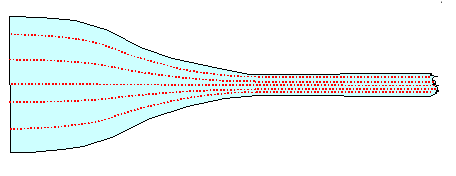 |
| Producing a "perfect" pattern from a striated wootz cake |
|
|
 |
We know that the distance between the cementite sheets should
be around 50 µm and that means that the distance in the striated wootz cake should
be correspondingly larger (around 500 µm=0.5 mm, say).
All you have to do is to precipitate large cementite particles
in the striated structure and that isn't too difficult if you already have small cementite particles or very strong carbide
formers in the desired structure. What you get after polishing / etching the surfaces might look like this in cross-section,
note the "shallow angle magnification" effect: |
| |
|
|
 |
Note that I'm not claiming that the real structure shown in these pictures is exactly what I have described above. The blade was actually made with the "Verhoeven
recipe" and the starting material may not have contained a striated cementite /
carbide former distribution.
However, Verhoeven would have a hard time to prove that this was not the case.
|
|
 |
Please note that in all three cases it is generally possible to make the structure
more pronounced by employing Ostwald ripening by cycling as described above.
|
|
 |
It should be clear by now that in our wootz blades we want to get the striated
distribution shown right above. It allows the smith to produce the more complex patterns by manipulating the geometry of
the cementite distribution during forging; I'll get to that. |
 |
In the third example here I have shown that a special structure in the wootz cake
or whatever starting material you use is one potential way for doing that.
Now let's look at other ways, in particular
Verhoeven's ideas. |
|
|
© H. Föll (Iron, Steel and Swords script)


