|
Grain Boundary - Advanced |
| |
Geometric Description of a Grain Boundary |
 |
For starters, we ask ourselves how we can describe the basic geometry of a nice
planar grain boundary. |
|
 |
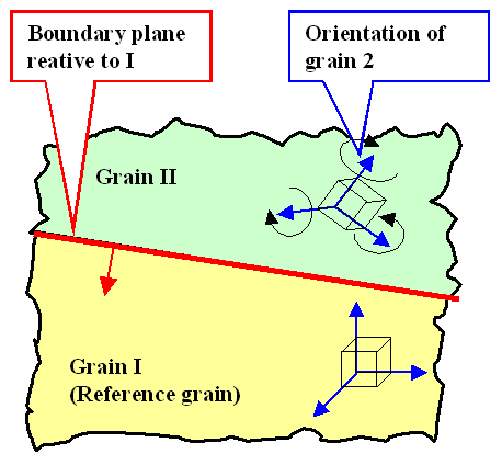
One way of tackling this is to cut (in your brain) one crystal
in a plane that is to become the grain boundary plane in the starting crystal 1. The cut-off part we rotate arbitrary amounts
around all three axes. Then we join the original crystal 1 with its rotated brother.
Of course, the two parts will
not fit, so we remove or fill in matter as required.
So how many numbers do you need to describe what we just did? How
many numbers are needed to describe the basic geometry of a planar grain boundary? |
| |
|
|
|
 | | The formal production of a grain boundary
|
|
| |
| |
|
 |
Let's make it short: We need 5 numbers to describe what we did: Three number (=rotation angles,
for example) to describe the relative rotation of the grains to each other, and two numbers to describe the position of
the grain boundary plane.
One is inclined to think hat one needs three numbers for determining the exact position of
the grain boundary plane too, since a normal vector perpendicular on this plane (the red vector in the drawing above) has
three components. Yes, but a normal vector has a defined magnitude and we don't care for that. The length on the vector
characterizing the grain boundary plane is unimportant, and that means that two numbers will do. |
 |
What we want to know about a grain boundary is its atomic structure and, related
to that, its energy
EGB (per cm2, of course). We have a formidable task ahead, because the quantities we
are after are functions of at least 5 variables! And that's only for the simple problem of a planar
boundary. If the grain boundary is curved, which it needs to be to enclose a grain, the two parameters characterizing the
grain boundary plane, become functions of the position. |
|
 |
Why do we want to know the grain boundary energy? Because the basic question we have is: |
| |
| |
| |
Are there special grain boundaries with
particular low energies?
|
|
| |
| |
|
 |
If there are, we might expect that crystals go for them; they want to minimize their (free) energy after all.
You might think that the question is moot, because
as soon as the first small crystallites form at some nuclei, their orientation is given. When those crystallites grow together,
the relative orientation of the grains is what it is. Nothing the crystal can do about it.
You are almost
right. The relative orientation of the grains is indeed whatever it is. But the crystal, being much smarter than you as
far as grain boundaries (and possibly a few other things) are concerned, still knows a trick or two about minimizing energy. |
| |
| |
| |
Minimizing Energy With Respect to the Grain Boundary
Plane |
 |
Let's start assuming that the orientation relation between the two grains is given.
The actual grain boundary still could be on any plane with respect to some coordinate system, for example the Bravais lattice
of grain 1. The specific and simpler question is now: Are there any special low-energy planes
for the given orientation?
You bet there are. Not that I can demonstrate this for any
orientation and any plane, but one example is enough to get the gist of the argument
across. |
| |
| |
| |
 |
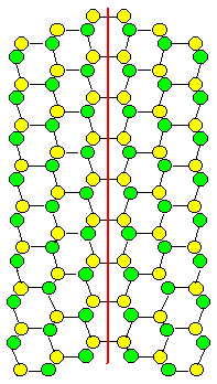 |
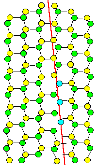
| Possible Boundary planes in a "diamond twin" |
|
| |
| |
|
 |
We are looking at a very special orientation between two grains of a crystal, called "twin" orientation. We have a diamond-structure, but twins work for any lattice: one grain
is simply the mirror image of the other one. Two grain boundary planes are shown and it is ridiculously obvious that the
one on the right is far, far "better", meaning it has a far lower energy then the one on the left.
On the
right, all atoms find partners at the proper distance and can bond happily. On the left, you can't even draw what is going
to happen. A lot of atoms around this boundary plane will be very unhappy. |
|
 |
It is clear that something like this happens for any grain orientation relationship, and that
there are always some special planes with lower energy than the rest. So what is the crystal going to do about this?
It will break up the boundary plane into properly oriented facets as shown
here. |
| |
| |
| |
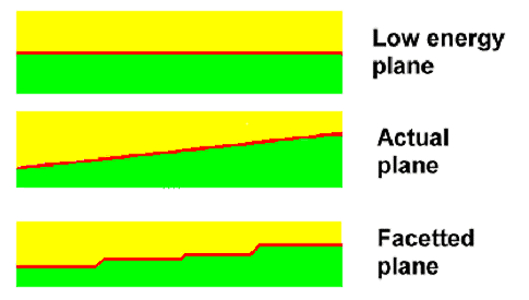 |
| Facetting of Grain Boundary Planes to Lower the Energy |
|
| |
| |
|
 |
All the crystal needs to do is to move a few atoms close to the boundary a little bit. This
is not difficult at high temperatures, when atoms are mobile.
|
 |
We might safely assume that grain boundaries will be facetted into low energy
planes. What kind of planes that are for some arbitrary orientation is not so easy to predict, however. Nevertheless, facetting
will happen. It might be on a scale so small that we don't see it easily but it will be there. No more needs to be said
about this topic. |
| |
| |
| |
Interlude: Making Low
Angle Grain Boundaries with Dislocations |
 |
Let's make the most simple grain boundary imaginable by using the recipe from above. What we do then is to cut the crystal in twain and rotate the upper part. To do that as simply
as possible, we rotate only around one axis and keep the rotation angle small. |
|
 |
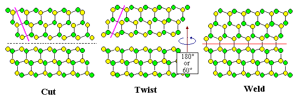
There are two basic ways of doing this, called "twist" and "tilt".
When you make a twist boundary, the axis of rotation is in the plane of the cut and the
future grain boundary, if you make a tilt boundary, the axis of rotation is at right
angles to the plane of the cut and the future grain boundary. An arbitrary boundary can then be made by combining twist
and tilt.
The figures below illustrate that. They also show that you can make one and the same
boundary in two ways, at least as far as the "twin boundary" in a diamond crystal is concerned that is shown once
more below. That doesn't prove that you can do that for all possible boundaries but makes clear that there could be some
complications with this recipe. Rest assured that there are! And that you really do not want to learn more about it.
|
| |
| |
| |
 |
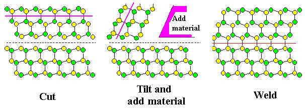 |
| Making the same diamond twin boundary in two ways, using either "twist" or "tilt" |
|
| |
| |
 |
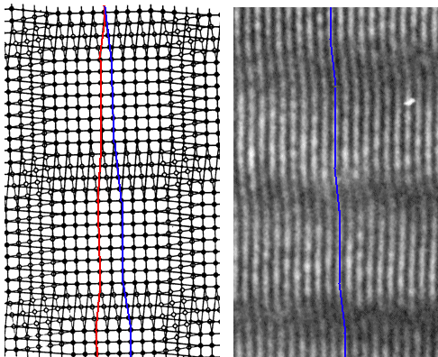
Here I only want to show that you can make so-called "small-angle" grain boundaries of all kinds by combining the two special periodic dislocation
arrangements that we get for either a pure tilt or a pure twist
small-angle grain boundary.
What is a small-angle grain boundary? Any boundary where you twist or tilt only by a few
degrees, so that the two grains have almost the same orientation.
Here is the way
it's done: |
| |
| |
| |
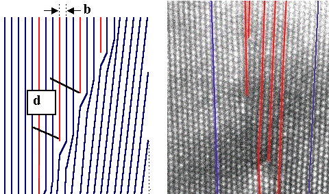 |
| Pure tilt small angle grain boundary; principle and the real thing |
 |
| Pure twist boundary; principle and the real thing |
| Source: The drawing in the lower left goes back, I believe, to Read
.The other pictures are mine. |
|
| |
| |
|
 |
Contrasted are schematic drawings and a HRTEM images of the real thing. In the lower picture,
just one set of screw dislocation is visible in the HRTEM image by the shift induced in the lattice planes above the grain
boundary plane.
Refer to the "science of dislocation" module
for general information and in particular to the screw dislocation stuff
|
|
 |
The way a tilt boundary "works" by employing edge dislocations is obvious. You just
need a parallel array of dislocation spaced at some distance that determines the tilt angle. For a twist boundary you need
a network of screw dislocations. It could be square as shown above or here, or hexagonal and complicated as in this
picture.
Of course, this simple approach only works for small misorientation angles of at most a few degrees; too
large an angle, and the dislocations have to get so close that it doesn't make sense anymore.
Mix the two kinds of dislocation
arrangements, and you get rather complex but well-defined and understood dislocation structures for any small-angle
grain boundary with some twist and some tilt. |
 |
This is complicated but the important thing to realize is why the crystal is actually
doing all this. It introduces dislocations for one reason only. All the mismatch caused
by having grains with different orientations is downloaded into just the core of the dislocations. In between the dislocations
the match of the two lattices is perfect. |
|
 |
In other words: The crystal prefers to have a large pain concentrated in a small area with
large painless regions in between to a large area with medium pain everywhere. Who wouldn't. Going shopping with your wife
in a major way once in a while is by far preferable to a bit of shopping all the time.
That will also be the guiding
principle for what to do in arbitrary large-angle grain boundary. |
| | |
|
| |
Structure of Arbitrary Grain Boundaries |
 |
There are infinitely many ways you can lie in bed. On your back, on your side,
legs pulled up or down, and so on. But a few well-defined positions are just a lot more comfy that all the others. There
are infinitely many ways you can orient a grain with respect to the other. But a few well-defined orientations just have
a lower energy than all the others. |
|
 |
The crystal knows what those particular comfy "low sigma" orientations
are: orientations where right at the grain boundary as many atoms as possible have the same position in grain 1 and in grain 2. And no, it doesn't matter where exactly the grain boundary is positioned; the
crystal can always make itself comfortable in this respect by facetting. |
|
 |
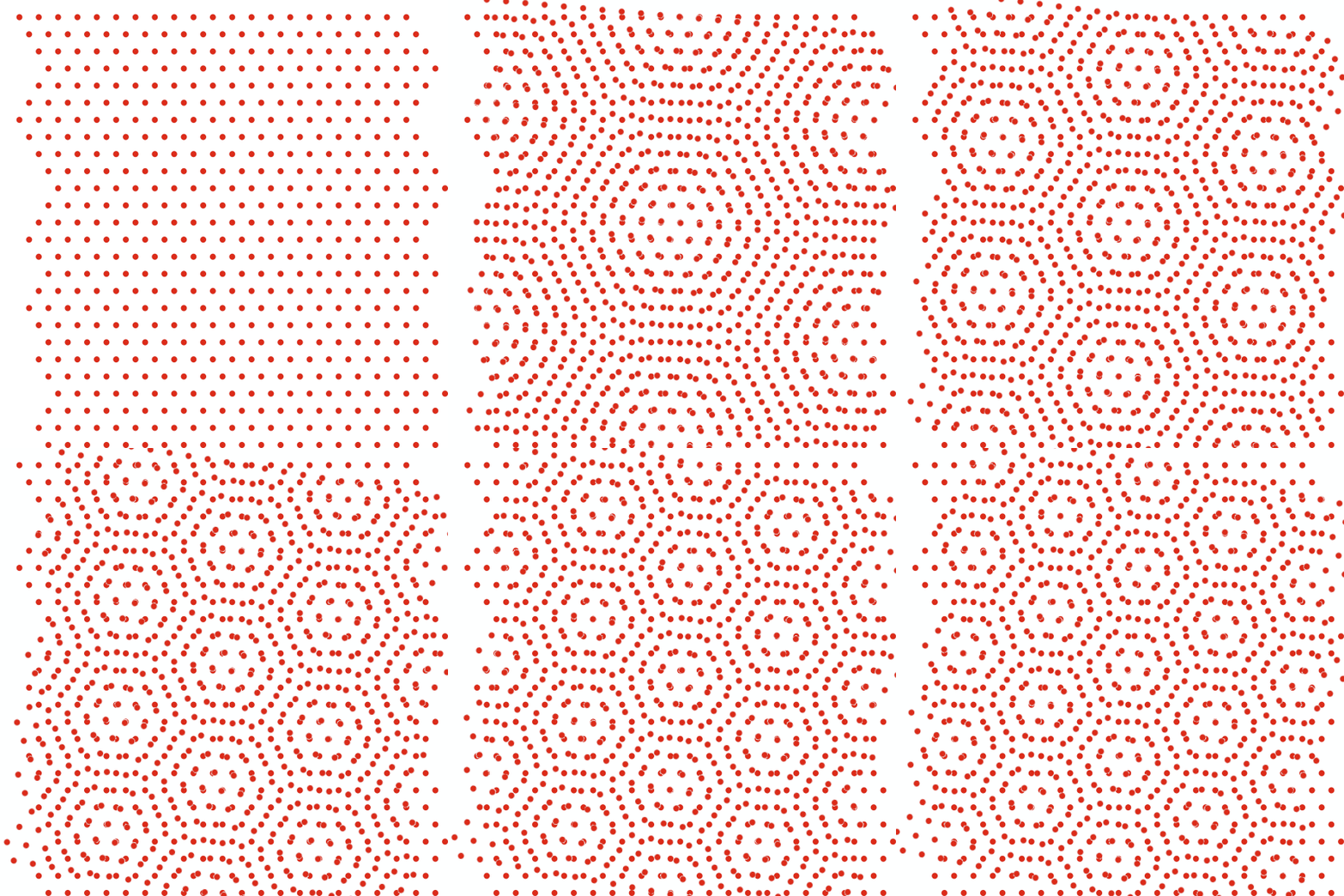
It is easy to get an idea about these special orientations. Look at the animation below. We
make a twist boundary but we won't stop at small angles.. |
| | |
|
|
|
|
| |
| |
|
 |
What you see is that at certain angles there is a perfect match of lattice points.
Put atoms there and they have the same position in both grains. |
 |
This can be generalized for general lattices and three dimensions; note that I
emphatically do not say "easily generalized". Just let two three-dimensional
lattices interpenetrate and rotate one in all directions. Calculating the lattice of coinciding points or the so-called
O-lattice, a name forever associated with W.
Bollmann, is not something lightly undertaken with just some high school math. And that's just the comparatively
simple beginning of calculating what kind of tricky
structure the crystal will now put up if it finds itself close to, but not exactly in, some preferred "low sigma"
orientation. |
|
 |
So what does that "low sigma" mean? Well, if there is some coincidence
between points of the two lattices, those points define a lattice, too. The volume of an elementary cell of this "coincidence site lattice" or CSL, divided by the volume of the elementary cell of
the crystal lattice, will always be an odd integer that is given the assignation sigma or S.
Our old friend, the twin boundary, now carries the assignation S3 boundary. |
|
 |
Here are drawings (of course only in 2 dimensions) of the S3
or twin boundary and a S5 boundary, the next best thing. |
| | |
|
|
|
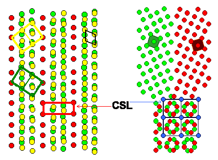 | Interpenetrating cubic lattices producing a
S3 and a S5 CSL or "Coincidence Site Lattice" |
|
| |
|
 |
But let's not go into details, e.g. why only odd-numbered sigma values exist,
but draw a simple conclusion: |
| |
| |
| |
There are special low-energy orientations.
The crystal will do something if it finds
one of its grain boundaries close to
such an orientation.
|
|
| | |
|
 |
What the crystal will do is to generate a dislocation arrangement that produces
a small-angle grain boundary in such a way that the additional "small angle" added to the basic large angle defining
the boundary, will orient the grain boundary in the exact low-energy and typically low-sigma
orientation. |
|
 |
It's the old principle. Invest some energy into the making of a dislocation network,
to gain a lot of energy because you now have a low-energy boundary. |
 |
There is a catch to this, however. The dislocation arrangement that by itself
would define a low-angle grain boundary needs to sit right in the actual large-angle boundary since it must belong to both
grains. But how do you define a dislocation in two lattices that are not connected in a continuous way? |
|
 |
You don't because you can't. That's why grain boundary dislocations are defined
in a new lattice, a lattice that is common to both grains. The coincidence site lattice
is common to both grains, so we could take that lattice and make a dislocations by the standard "cut-and-shift"
procedure. You would make monster dislocations in this way, because you need to shift a large amount since the CSL lattice
is always much larger than the lattices of the crystals. Dislocations in the CSL lattice would have large Burgers vectors,
in other words. If you would do that (and I leave open how you would do that in a real grain boundary in a real crystal
and not just on a piece of paper), you would be in for a surprise. Your monster dislocations would split into a bunch of
"small" dislocations with small Burgers vectors. Those are what we call "grain
boundary dislocations".
They can do this because if you look closely at the geometry once more, you recognize
that there is another lattice common to both crystals with unit vectors smaller than the actual crystal lattice. It is called
the "DSC"
lattice for "displacement shift complete". Not the best of all possible names, but that's what it is called. Just
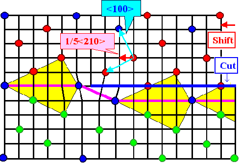
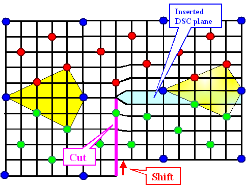
for the hell of it, I show you two of these dislocations (edge type) in a S5 boundary: |
| | |
|
|
|
 |
 |
| Grain boundary dislocation in a S5 boundary |
|
| | |
|
|
 |
The red points belong to lattice 1, the green ones to lattice 2. The blue ones
are common in both lattices and thus define the coincidence site lattice. The black lines constitute the DSC lattice; here
it is simply the lattice common to all lattice points. A cut (blue or pink line) combined with a shift (red vector) produces
an (edge) dislocation in the DSC lattice. This dislocation moves the boundary as shown, the yellow "structure units"
illustrate that.
Imagine a regular array of these dislocations, and you have a small angle boundary superimposed on
the S5 boundary. If the real boundary would have been off the S5
orientations by a small angle, it now would be turned into the precise S5 orientation. |
 |
All crystals do that all the time. They have no problem in figuring out the best
way to restructure their boundaries in the way described above. And that's why we see all these "grain boundary dislocations"
all the time in our electron microscopes. |
|
 |
We know why these dislocations are there in principle. However, if we want to
calculate the details, it gets hellishly difficult. Be happy that I won't go into how it is done. |
| | |
|
© H. Föll
© H. Föll (Iron, Steel and Swords script)


