 |
We have already seen that there is more
than one way to make a MEMS gyro. Here we look at a concept that is used quite a bit and pursued at the ISIT,
the Fraunhofer Institute for Si Technology in Itzehoe, a partner
of the Inst. of Materials Science and Technology of the CAU. |
|
 |
The basic concept is to use the Coriolis force,
always present in rotating systems, to induce a response in a moveable mass held by springs. |
|
 |
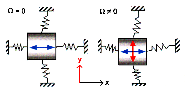
This is done by having a mass suspended on two orthogonal set of springs as schematically
shown below. The mass is driven by some mechanism to oscillate in x-direction with constant amplitude. The
frequency of the driving force is chosen in such a way that the system is close to its resonance
frequency to ensure large amplitudes and therefore signals. As long as the the car or whatever moves with constant speed
(in the x-y-plane to keep things easy), that is all that happens: The sensor mass oscillates
in x-direction only. |
|
|
Picture courtesy of ISIT |
|
 |
If we now imagine some rotation with angular velocity W
around the z-axis perpendicular to the x-y-plane (our car is driving into a curve)
a Coriolis force FCor develops, given by
|
| |
|
|
 |
This Coriolis force drives our mass into the y-direction and thus
will produce an oscillation in y-direction as shown above. The oscillation amplitude in y-direction
then will "somehow" be coupled to the angular velocity W. Again, we try to work
under resonance conditions because that gives higher sensitivity. |
|
 |
The resonance frequencies of the two oscillation modes (one in x-direction,
the other one in y-direction) do not have to identical. In fact, we will take care to make them somewhat different. |
 |
So all we have to do now is to "somehow" measure the amplitude of the
y-direction oscillation and figure out how it relates to W Also, not to
forget, we have to figure out how todrive the oscillation in x-direction with constant amplitude "somehow".
And after all that figuring is done, we have to make and package the system "somehow" - and sell it for 10
€ or so. |
|
 |
For the first "somehow" we need a lot of physics and Math. At the most
simple level we need to delve into the "driven
damped
linear oscillator" theory, contained in the following differential equation
expressing Newtons first law: |
| |
| m · |
d2x
dt2 |
+ kF · m · |
d x
d t |
+ ks · x |
= |
F0 · cos(wD · t)
|
|
|
|
 |
We have m=mass of the oscillating body, kF=friction
or damping constant, ks=spring constant, F0=amplitude of the driving force,
wD=frequency of the driving force. |
|
 |
This is a standard problem in more elementary mechanics and this link contains all you actually should know about this. Solving
the equation gives the momentary location x(w, t), the amplitude X0(w), and the velocity v=dx(w, t)/dt
needed in the Coriolis force equation. |
|
 |
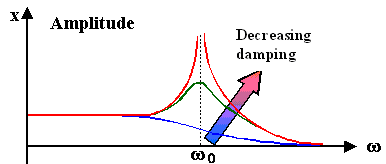
Looking just at the amplitude of a driven damped linear oscillator, we have the
following, hopefully familiar picture: |
|
|
|
|
 |
Depending on the degree of damping or friction, we will have very large to relatively
small amplitudes at the resonance frequency w0 |
|
 |
Obviously we need to know m, ks, and kF
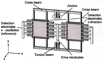
to go on. So let's look at an actual gyro in a very simple and by now (2007) outdated version: |
| |
 |
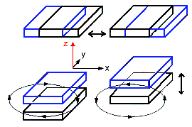 |
The two oscillation modes.
The ellipses shows the combined effect |
| Pictures courtesy of ISIT |
|
 |
First thing to realize is that the oscillating mass is not the orderly mass point of basic mechanics but some extended piece of probably Si with a complex shape.
The second thing to realize is that there are no neat little springs. The "beams" that define parts of the oscillating
mass are also part of the "spring". |
|
 |
Being sophisticated Materials Science students, we know that the points raised
above are no major problems. There are ways to calculate (numerically if necessary) how that contraption oscillates. The
"spring" results from the mechanical properties of Si; Young's modulus will come up for sure. That takes care
of m and ks "somehow". |
|
 |
Good enough. But what about the kF, the friction or
damping constant? Now we are in deep water - or can you make an educated guess on that topic? No, you cannot - neither can
I. Suffice it to say that the main friction or energy
dissipation mechanism, is "air damping" i. e. the kind of damping you experience if you fawn a fan around. |
|
 |
That offers an opportunity and a problem: Adjusting the pressure
inside the packaged chip allows to pick just the right damping for optimal functionality (that we "somehow" determined).
That is the opportunities and that is what we actually really do. The problem is: How can you guarantee that this pressure
will stay at its necessary value for 20 years or so? This is a first aspect of one of the tougher problems in MEMS:
How to ensure long-time reliability. |
| |
|
 |
And we haven't even discussed how the driving and the signal detection works.
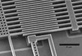
But that is obvious from just looking at the picture above or the detail of the drive given below: |
| | |
| |
|
 |
Driving the oscillation is obviously done
electrostatically. The fixed part of the comb is supplied with some alternating voltage, changing the charge from plus to
minus at the driving frequency, while the movable part is kept at a fixed charge=potential. This will lead to alternating
attractive and repelling forces - the oscillator is driven accordingly |
|
Picture courtesy of ISIT |
|
|
 |
Detection is done capacitively. The interdigitated finger structure at the outside for the
reference signal detection is just a capacitor with an (alternating) capacity that depends on how deeply the fingers penetrate
in the x-direction, | |
|
 |
The two "large" plate under the outside fingers also form a capacitor with an (alternating)
capacity that depends on how far the fingers are away in the z-direction. |
|
|
 |
In total we get easy-to-process AC signals with frequencies around the two resonance frequencies
of the major oscillation modes. One signal we use for a feed-back loop that keeps the oscillation amplitude in the x-direction
constant (or at whatever value we like), the other one contains the information we are after: the angular velocity W. | |
| | |
| |
© H. Föll (Semiconductor Technology - Script)

