 |
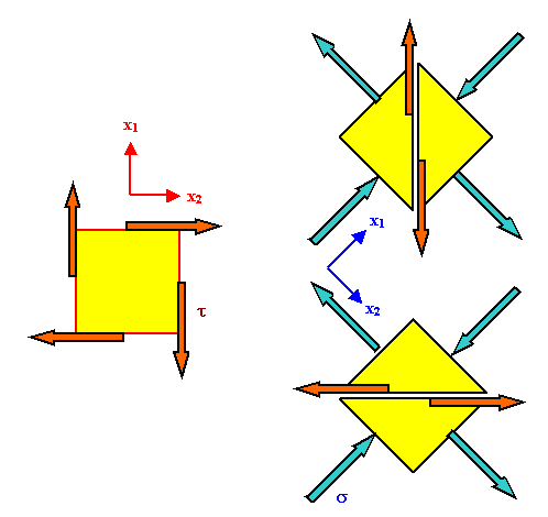
The picture below shows how a transformation of the coordinate system can produce pure shear stress on the chosen planes of your material for pure normal
stresses in the new system. |
|
 |
Since coordinate transformations are not without some problems, let's discuss what we see
in the figure. |
| |
|
 |
The situation on the left is pretty much what we introduced as pure
shear strain before. The coordinate system is shown in red. |
|  |
Now we change the coordinate system to the blue one - we rotate the coordinate
system by 45o. |
 |
We do not rotate the body of material, however!. The yellow
squares shown are unit squares of the coordinate system, not a piece of the material. |
|
 |
The blue vectors denoting the force that belongs to the stress on the unit square are obtained by using
the proper transformation formulae for the stress tensor. |
|
 |
On the chosen planes of the material, which are the same and not rotated,
we have the same shear stress as before. This is most easily realized if we use the "cutting"
procedure; shown by dividing the unit square in triangles. |
|
 |
The forces we need to apply to the surface of the cut is a pure shear force; this is true, as shown, for
both orientations. |
 |
Simple vector addition (and taking into account the different size of the areas) tells us that
the shear stress t acting on the "old" plane in the new system is |
| |
|
|
 |
See also the module dealing with the relation of Youngs
modulus and the shear modulus, where more detailed information is given. |
|
| |
© H. Föll (MaWi 1 Skript)

![]() 7.2.2 Einige Definitionen und Saetze
7.2.2 Einige Definitionen und Saetze ![]() Beziehung zwischen E-Modul und Schermodul
Beziehung zwischen E-Modul und Schermodul