 |
We will first investigate the interaction between two straight
and parallel dislocations of the same kind. |
|
 |
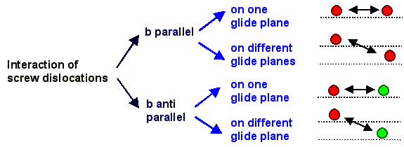
If we start with screw dislocations, we have to distinguish the following cases: |
| |
|
 |
In analogy, we next must consider the interaction of edge dislocations, of edge
and screw dislocations and finally of mixed dislocations. |
|
 |
The case of mixed dislocations - the general case - will again be obtained by considering
the interaction of the screw- and edge parts separately and then adding the results. |
 |
With the formulas for the stress and strain fields of edge and screw
dislocations one can calculate the resolved shear stress caused by one dislocation on
the glide plane of the other one and get everything from there. |
 |
But for just obtaining some basic rules, we can do better than that. We can classify
some basic cases without calculating anything by just exploiting one obvious rule:
|
|
 |
The superposition of the stress (or strain) fields of two dislocations that are moved
toward each other can result in two basic cases: |
|
 |
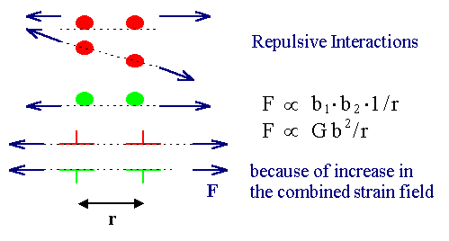
1. The combined stress field is now larger
than those of a single dislocation. The energy of the configuration than increases and the dislocations will repulse
each other. That will happen if regions of compressive (or tensile) stress from one dislocation overlaps with regions of
compressive (or tensile) stress from the other dislocation. |
|
 |
2. If the combined stress field is lower than
that of the single dislocation, they will attract each other. That will happen if regions
of compressive stress from one dislocation overlaps with regions of tensile stress from the other dislocation |
 |
This leads to some simple cases (look at the stress
/ strain pictures if you don't see it directly) |
|
 |
1. Arbitrarily curved dislocations with identical
b on the same glide plane will always
repel each other. |
| |
|
|
 |
2. Arbitrary dislocations with opposite
b vectors on the same glide plane will attract
and annihilate each other |
|
|
|
|
 |
Edge dislocations with identical or opposite Burgers vector b on neighboring
glide planes may attract or repulse each other,
depending on the precise geometry. The blue double arrows in the picture below thus may signify repulsion or attraction. |
| |
|
 |
The general formula for the forces between edge dislocations in the geometry shown
above is |
| |
| Fx | = |
Gb2
2p(1 –n)
| · |
x · (x2 – y2)
(x2
+ y2)2 |
| Fy | = |
Gb2
2p(1 –n)
| · |
y · (3x2 + y2)
(x2
+ y2)2 |
|
|
|
 | For
y = 0, i.e. the same glide plane, we have a 1/x or, more generally a 1/r dependence
of the force on the distance r between the dislocations. |
|
 |
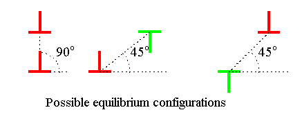
For y < 0 or y > 0 we find zones of repulsion and attraction. At some specific positions
the force is zero - this would be the equilibrium configurations; it is shown below. |
|
 |
The formula for Fy
is just given for the sake of completeness. Since the dislocations can not move in y-direction,
it is of little relevance so far. |
|
|
|
 |
The illustration in the link gives a quantitative picture of the forces acting on one dislocation on its glide plane as a function of the
distance to another dislocation. |
© H. Föll (Defects - Script)


