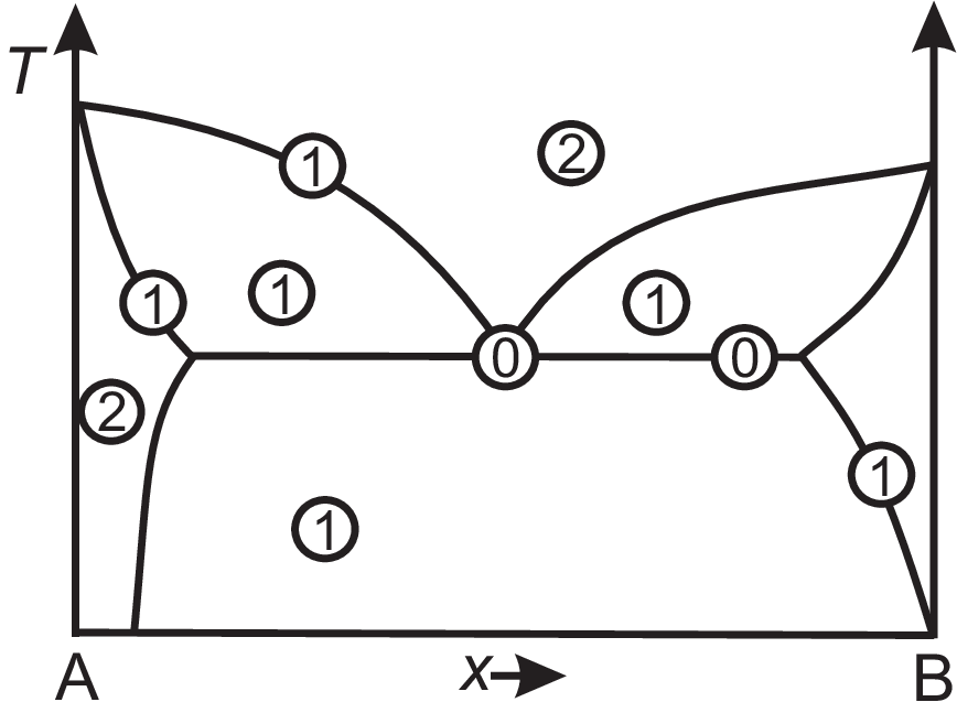
A (binary) phase diagram shows the regions of different phases typically in a \(p-T\) diagram or a \(T-\) (resp. \(p-\)) \(x\) diagram. A phase represents a uniform state of matter with respect to composition and physical state. Many essences of phase diagrams can be summarized by the Gibbs phase rule \(P + F = C + 2\) which holds at each point of a phase diagram. Here \(P\) is the number of phases, \(F\) the degree of freedom, and \(C\) the number of independent components. For a \(T-x\) phase diagram \(p\) is still an additional degree of freedom, so the phase rule reads \(P + F = C + 1\). Examples are shown in Fig. 2.5. The horizontal line (tie line) through the eutectic point (i.e. \(T\) is fixed) implies \(F = 0\) We will discuss this in detail in section 2.9. The oblique lines have \(F = 1\) since \(T\) or \(x\) are variables. The single phase field has \(F = 2\) (one can vary \(T\) and \(x\) and stays within this field). The two phase fields have \(F = 1\), i.e. when selecting \(T\), the composition of the phases is fixed due to the lever rule (see below). Obviously most of the areas show phase separation. In what follows we will discuss several reasons for phase separation.

© J. Carstensen (TD Kin II)