 |
First, lets consider the dynamic behavior of a simple pn-junction.
|
|
 |
Whereas the small signal behavior at low frequencies
is exactly that of the example given before, the large
signal response in practice is simply what we (and everybody else) calls the switching
behavior of the diode. In other words, we are looking at either
- Suddenly switching the voltage from 0 V to some forward value Uf , or
- Suddenly switching the current from 0 A to some constant forward value If .
|
 |
In order to have some idea of what we want to find out, here are some typical
results of experiments with modulated inputs. First, we look at the small signal behavior
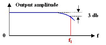
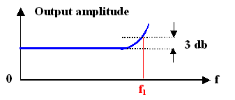
by plotting the amplitude of the current output versus the amplitude of the voltage input as a function of the frequency. What we will find looks like this: |
| |
| |
|
|
 |
While real curves may look quite different, we always will find that with increasing
frequency the output amplitude will eventually come down or go up. Often, the frequency where the output value is 3 db
below or above its low frequency value is identified as some limit frequency fl, giving us a time
constant t = 1/f l which we want to understand in terms of materials
properties. |
 |
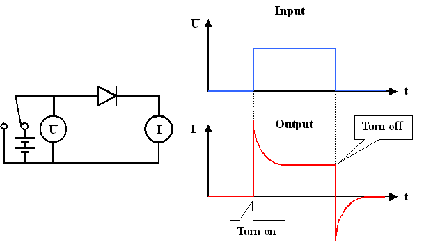
Now we look at the switching behavior for the voltage,
i.e. we suddenly switch off the voltage across the diode from 0 V (or some reverse voltage) to some forward voltage,
e.g. 0,7 V. |
|
 |
This is experimentally easy to do and to measure. What we obtain looks like this: |
| |
|
|
 |
We have pronounced current "transients"
describable by one (or possibly more) time constants; and we want to know how these time constants relate to materials properties
of the pn-junction. |
 |
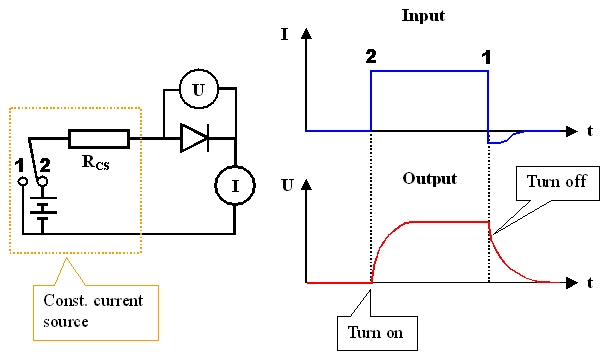
Next, we switch the current
"suddenly". The question is how to do this. In formal electrical terms, we just take a "constant current
source" and turn it on. In reality this might be a voltage source with a resistor RCS much larger
than anything else in the circuit. The current than is simply U/ RCS and switching is obtained by switching
the voltage which now could be rather large. |
|
 |
If we do the experiment, we will observe the following behavior: |
| |
|
|
 |
Again, we have transients
in the diode behavior, this time the voltage is affected. But we also have a kind of transients in the current - we
will not be able to switch it off abruptly, but for some time a reverse current
flow will be observed |
|
 |
Since the current pulse was "made" by a (rectangular) voltage pulse
and the external voltage is zero after the switching, we are forced to conclude that the diode acts for some time as a voltage/current source after the primary voltage was turned off. More
details can be found in an advanced module |
 |
Once more we measure some time constants and we must ask ourselves how they relate
to the time constants of the voltage switching experiment and to material parameters. |
 |
Accepting all these "experimental" findings, we even must conclude that
there might be several time constants which, moreover, might depend on the particulars
of the experiment, e.g. the working point, or the amplitudes of the input signal. |
|
 |
This does not just look a bit involved; it
really is. And the "ideal" pn-junction diode is about the most simple
device we have. |
 |
We are going to look at it in some detail in the next subchapters, even so we
are not particuarly interets in plain pn-junctions. But this will help to develop some basic understanding of the
underlying processes and make the dicussion of more involved devices easier. |
© H. Föll (Semiconductors - Script)


