 |
Phase diagrams are the mainstay of materials science and technology. They may be seen as a
map in temperature - composition space that shows the particular structure with the
minimum free enthalpy at any point of the "map". |
|
 |
If we take the formula
for the equilibrium concentration of self-interstitials to also describe the equilibrium concentration of extrinsic
interstitial atoms if we replace the formation enthalpy by a corresponding property (lets call it solubility
enthalpy), the resulting diagram of the equilibrium concentration over temperature can be interpreted as part
of a phase diagram. |
|
 |
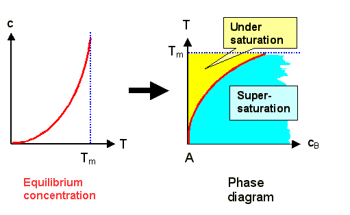
All we have to do is to switch the axes from the normal representation concentration
vs. temperature to temperature vs. concentration: |
| |
|
 |
We now have a diagram for the composition of material A (the matrix) with material B
(the extrinsic interstitial) for small concentrations of B. |
|
 |
The red line denotes the limit of solubility of B in A; it corresponds to the equilibrium concentration.
|
|
 |
In the yellow or blue areas, the B-interstitials are undersaturated
or supersaturated, respectively. We must expect that something new is going to happen
in the supersaturated region, e.g. the precipitation of some AxBy compound, or a phase separation
of A and B. |
|
 |
On the other end of the composition axis, things would be much the same, only that now A is the
interstitial in B. The equilibrium line and the melting point would be different too, of course. |
 |
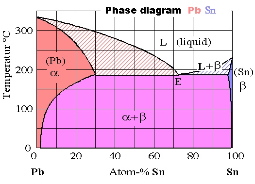
The phase diagram Pb - Sn (familiar solder) provides a real example: |
| |
|
 |
Pure lead and lead with Sn interstitials has a fcc lattice; we call this the
a-phase; pure Sn and Sn with Pb interstitials is tetragonal, we call
this the b-phase. |
|
 |
In the supersaturated region something new has happened ndeed, we have an eutectic
phase separation and a mixture of a and b. |
|
 |
In the high temperature regime, we have something new, too: Mixtures of liquid (L) and solid phases |
 |
Be that as it may (and it can be much more complicated), the essential points are |
|
 |
The system always goes for the minimum free enthalpy, and this minimum could be calculated in principle
following the same, albeit much more involved line of reasoning we employed for equilibrium concentrations of point defects. |
|
 |
The (experimentally determined) phase diagrams are maps of the particular minimum free enthalpy configuration
out of many possible arrangements for a given composition and temperature. |
|
 |
Changing the temperature or the composition of a system thus takes us from one area in the phase diagram
to another; the boundaries we have to cross give us an idea of what has to happen kinetically. |
| | |
© H. Föll (Defects - Script)


![]() 2.2.1 Extrinsic Point Defects and Agglomerates
2.2.1 Extrinsic Point Defects and Agglomerates