
Download/Show PDF-File of paper (860 kByte)
Download/Show PDF-File of presented poster (3.1 MB)
CELLO: AN ADVANCED LBIC MEASUREMENT FOR SOLAR CELL LOCAL CHARACTERIZATION
J. Carstensen, G. Popkirov, J. Bahr, and H. Föll
Faculty of Engineering
Christian-Albrechts University of Kiel, Kaiserstr. 2, D-24143 Kiel, Germany
ABSTRACT: With the help of an extremely stable potential/current source the linear response (current changes as well as potential changes) to an intensity modulated local additional illumination of a solar cell is measured in the CELLO system for various fixed global conditions. This allows to obtain a large number of independent data at each point of a solar cell. Fitting this data to an advanced model yields a set of local parameters for each point on the solar cell which allow to calculate local IV-curves. Theoretical and experimental techniques will be discussed and the applicability of this new tool will be demonstrated.
Keywords: Defects -1: Shunts -2: Modeling -3
1. INTRODUCTION
The global IV-characteristics of any solar cell results from the local properties of the device. Any variation of a local parameter, e.g. a locally changed shunt or series resistance, may adversely influence the global properties. A global solar cell thus must be described by a complicated network of locally varying parameters like diffusion length L, serial resistance RS of grid and emitter, and shunts RSh. For the optimization of solar cell technology, but also for the simulation of the global performance upon changing one of the many parameters, all local properties and an adequate network model must be known.
So far, however, it was not possible to measure all local properties of a solar cell. Only the local photo current can be measured with an adequate tool (the standard LBIC-system [1, 2]) which usually is employed under short-circuit current conditions and then allows to calculate the local diffusion length L(x,y) of the solar cell material from the local photo current IPh.
A few other techniques (e.g. MASC [3], and IR-thermography [4]) allow for a local identification of nonrecombinative defects, but the new characterization technique "CELLO" is, to the best of our knowledge, the first tool that allows to measure all local parameters, especially the local series- and shunt resistance RS(x,y) and RSh(x,y), and thus to identify all material- and process-induced defects. In principle, the data obtained could also be used to simulate the behavior of the complete solar cell for any set of technology parameters.
2. THE MEASUREMENT TECHNIQUE
The CELLO technique essentially measures the global response of a solar cell to local perturbations for several pre-set working points of the cell. The data obtained are fitted to a complete (and partially novel) model of the solar cell which allows to extract the local parameters. In particular, the solar cell is illuminated homogeneously, the global current Icell or voltage Vcell is kept constant at a preset value, and a sinusoidally modulated scanned laser beam with an amplitude (expressed as current) dIPh provides the local perturbation. The linear global current response dI under potentiostatic control, or the linear potential response dU under galvanostatic control, respectively, is measured for several points of the global IV-characteristics of the illuminated solar cell using a Lock-in technique. This is illustrated in Fig. 1. CELLO, in essence, thus works by analyzing the small (= linear) s ignal response of the "system" solar cell.
Taking several sets (= maps) of the quotients dI/dIPh (Vcell,x,y) and dV/dIPh (Icell,x,y) for a set of constant values Vcell or Icell allows to calculate all local parameters and the construction of the complete local IV-curve for each pixel of the solar cell. The well-known LBIC mode in this context is just the measurement of dI/dIPh(0,x,y).
The technical problems encountered with this approach are quite formidable, however. Measuring small signals, for example, demands to extract some µA currents from a background of about 1A. This means for starters that the intensity of the global illumination must be extremely constant which, somewhat surprisingly, proved to be rather difficult to achieve. Because the maximum current amplitude dI is restricted to £ 100 µA (which, for the spot illuminated, would not be a small signal anyway), a signal to noise ratio of 1:105 must be maintained and this demands extremely stable voltage and current sources.
Taking measurements at about 100.000 points for sufficient spatial resolution in several modes results in about half a million data points, so time is an issue. The major time limiting factor is the integration time of the Lock-in amplifier which defines, among other factors, the signal to noise ratio.

Figure 1: At several points along the IV curve of a solar cell the linear response of the current (potentiostatic control) or of the voltage (galvanostatic control) to an additional local illumination is measured.

Figure 2: The CELLO system.
The integration time for a constant signal to noise ratio decreases with increasing modulation frequencies of the laser; the usable frequency range, however, is limited; mostly by the capacitance of the pn-junction of the solar cell which essentially short-circuits high frequencies. In practice, the optimum frequency depends somewhat on the solar cell under investigation, but should be £ 1kHz.
Since very small (series) resistance's are to be measured, it is essential to provide good contacts to the cell; it is advisable to use separate current and voltage leads.
Fig. 2 shows a schematic drawing of the CELLO measuring apparatus; the exclamation marks denote crucial components.
The system realized so far is mostly custom built and averages about 10 measured points per second. The laser beam is focussed to about 100µm diameter. The potentiostat allows for 2.3 A (5V) current with a stability of some µA (µV) in a frequency range up to 10 kHz.

Figure 3: Equivalent circuit for the interpretation and evaluation of the CELLO measurements.
3. MODELING AND CALCULATIONS
Assuming that sufficient data sets have been obtained experimentally, the raw data must be converted into the local parameters of the solar cell. This is done with the help of the equivalent circuit diagram shown in Fig. 3. First, the solar cell is divided in a global part (denoted "complete solar cell"; on the left) and a local part on the right which are distinguished by different sets of parameters for the respective elements. Since we are locally looking at a very small part of the global cell, the global part is described by a constant set of parameters to which any local part (with a locally changing set of parameters) can be added without changing the global values in a sufficiently good approximation. In a conventional equivalent circuit diagram both parts would be connected via one resistor; but this proved not to be sufficient for the present task. There are two important modifications in the equivalent circuit shown in Fig. 3 with respect to conventional diagrams:
![]() (1)
(1)
This equation essentially describes the lateral diffusion and recombination of minorities and expresses a sensitivity of the solar cell to gradients of the diffusion length (cf. Fig. 5)
The impetus for this modification has sound physical reasons, but stems primarily from the impossibility to fit the experimental data to a simpler diagram. Since the complete equivalent circuit diagram and therefore the complete local characteristics can be calculated from a finite set of experimental data, additional data sets, if added to the fitting procedure, should not change anything. This requirement imposes constraints on the equivalent circuit which could only be met (but then very well) if the two adjustments described above were made.
The complete set of equations (under the assumption that the grid is an equipotential surface) is
![]() (2)
(2)
 (3)
(3)
![]() (4)
(4)
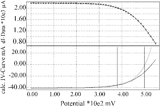
Using approximations to linear order in the additional local photo current, this set of equations is generally sufficient to extract all required quantities by fitting the experimental data. Two examples are shown in Fig. 4 which demonstrate the quality of the fit of the experimental data to the equivalent circuit of Fig. 3. The absolute values as well as the potential dependence of the CELLO results differ strongly on both areas of the solar cell. The measurement is extremely sensitive to local defects in the solar cell and therefore often shows drastic changes for the local IV-curves on a solar cell.
A)
B)

Figure 4: The lower part shows the calculated local IV-curves (black line) and the IV-curves of the complete solar cell (gray line). A) In a homogeneous area of the solar cell both IV-curves almost coincide; B) In a bad area of the solar cell the local IV-curve shows a strongly decreased photo current and a large serial resistance. The upper part in both cases shows many measured linear current responses (crosses) in comparison to the calculated values from a few measurements for different potentials.
Since it takes many hours to measure many sets of data, a special routine has been developed that allows to identify areas of interest with one measurement. After tedious transformations of Eq. (1) – (4) using some minor simplifications, an important analytical result for current measurements in forward bias emerges:

The parameters on the left side are directly measurable:
![]() is the standard LBIC current;
is the standard LBIC current;
![]() is the current response,
preferably at the optimal working point of the solar cell, and
is the current response,
preferably at the optimal working point of the solar cell, and
![]() is the slope of the IV-curve of
the complete solar cell at this working point. The plot of Eq. (5) indicates
areas with non-trivial deviant behavior with respect to the serial resistance
RL, the local diode
ID and/or increased local recombination of
minority carriers due to lateral gradients in the diffusion length distribution
(indicated by CREC). Thus this plot marks the
areas with possible defects where further measurements could be fruitful.
is the slope of the IV-curve of
the complete solar cell at this working point. The plot of Eq. (5) indicates
areas with non-trivial deviant behavior with respect to the serial resistance
RL, the local diode
ID and/or increased local recombination of
minority carriers due to lateral gradients in the diffusion length distribution
(indicated by CREC). Thus this plot marks the
areas with possible defects where further measurements could be fruitful.
Since for many homogeneous solar cells the relation
 (6)
(6)
holds, i.e. the slope of the local IV-curve is comparable with that of the global IV-curve and no enhanced lateral recombination processes occur, a plot of the left-hand side of Eq. (5) yields directly the (most important) series resistance of the solar cell.
Even more simplified, the function
 (7)
(7)
contained in Eq. (5) is already very sensitive to possible defects. Taking UA = 0 (LBIC-mode) the map of F is sensitive only to defects which are not related to simple bulk recombination which now can be further investigated by a complete analysis as demonstrated in Fig. 4.
4. RESULTS
First, the importance of Eq. (1) shall be demonstrated. Fig. 5 shows the calculated small signal response from an area with large gradients in the diffusion length with and without the correction of Eq. (1). in comparison with the measured values. Without the correction term, the fit is miserable while almost perfect it is included.
The physical reason for this term stems from the fact that not all carriers photo generated close to the surface are converted to current if a finite voltage is used. Some carriers are needed to generate the voltage and these carriers diffuse in the bulk and thus experience recombination in areas laterally removed from their "pixel". If the diffusion length varies laterally, this will then influence the local properties of the pixel. A mathematical analysis of this effect then leads to the (simplified) Eq. (1). As a general result it can follows that the average diffusion length of solar material is not a sufficient measure of the material quality; the gradients in the diffusion length distribution are just as important.
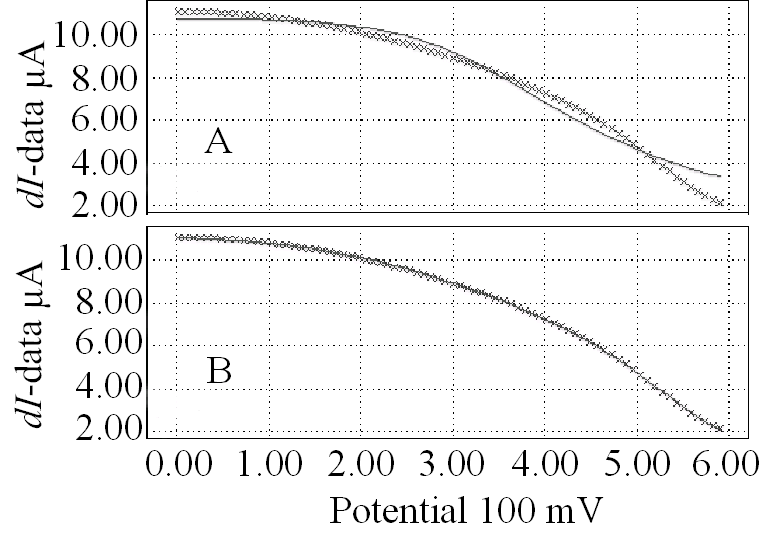
Figure 5: Fit of the linear response data. A: without lateral diffusion compensation; B: with lateral diffusion
The possibility to obtain complete local IV- characteristics enables to analyze yield detracting problems of all kinds in great detail; lack of space, however, does not allow in-depth case studies. Fig. 6 presents one example of a simple analysis with direct maps of the small signal response for dIsc (identical to a LBIC map), dIa (the index a referring to the optimal working point of the solar cell; cf. Fig. 1), dUoc (linear response of the potential at open circuit condition, cf. Fig. 1) and the map of F(sc,a) (c.f. Eq. (7)) which displays the "ratio" of dIsc and dIa which, according to Eq. (5) and (6), is sensitive to the serial resistance. Enlargements of the upper right hand side corner are included and compared to optical micrographs from the numbered points of interest. While visible defects can be found in this case, it must be emphasized that there are m any visible defects without corresponding features in the small signal maps and often prominent structures are seen in the maps without any visible origin. CELLO thus allows to mark the relevant defects for the solar cells only, which then may be further investigated with e.g. microscopic tools or more CELLO measurements (top down principle).
It is evident that the F(sc,a) plot shows many problems of this cell in good contrast. As is obvious from the optical micrographs, most of the defects are related to the serial resistance. The defects therefore coincide with the areas of least response in the dUoc map. Note the two inactive grid fingers (one marked "4" and shown in the micrograph as not connected to the main grid), the generally increased resistance around the edge and the white spots corresponding to scratches ("1" and "2") or particles shortening the pn-junction, and the defective AR-coating ("3"); cf. the micrographs in Fig. 7. In conclusion, most of the defects in this solar cell are process induced.
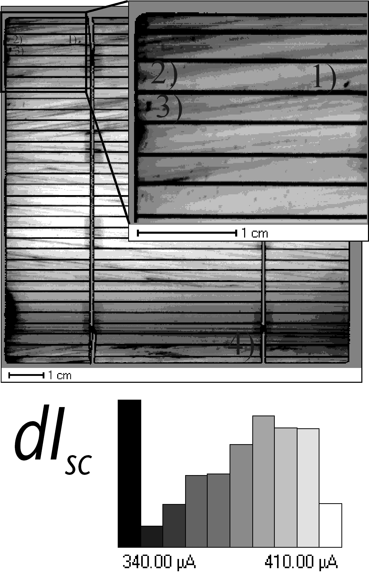
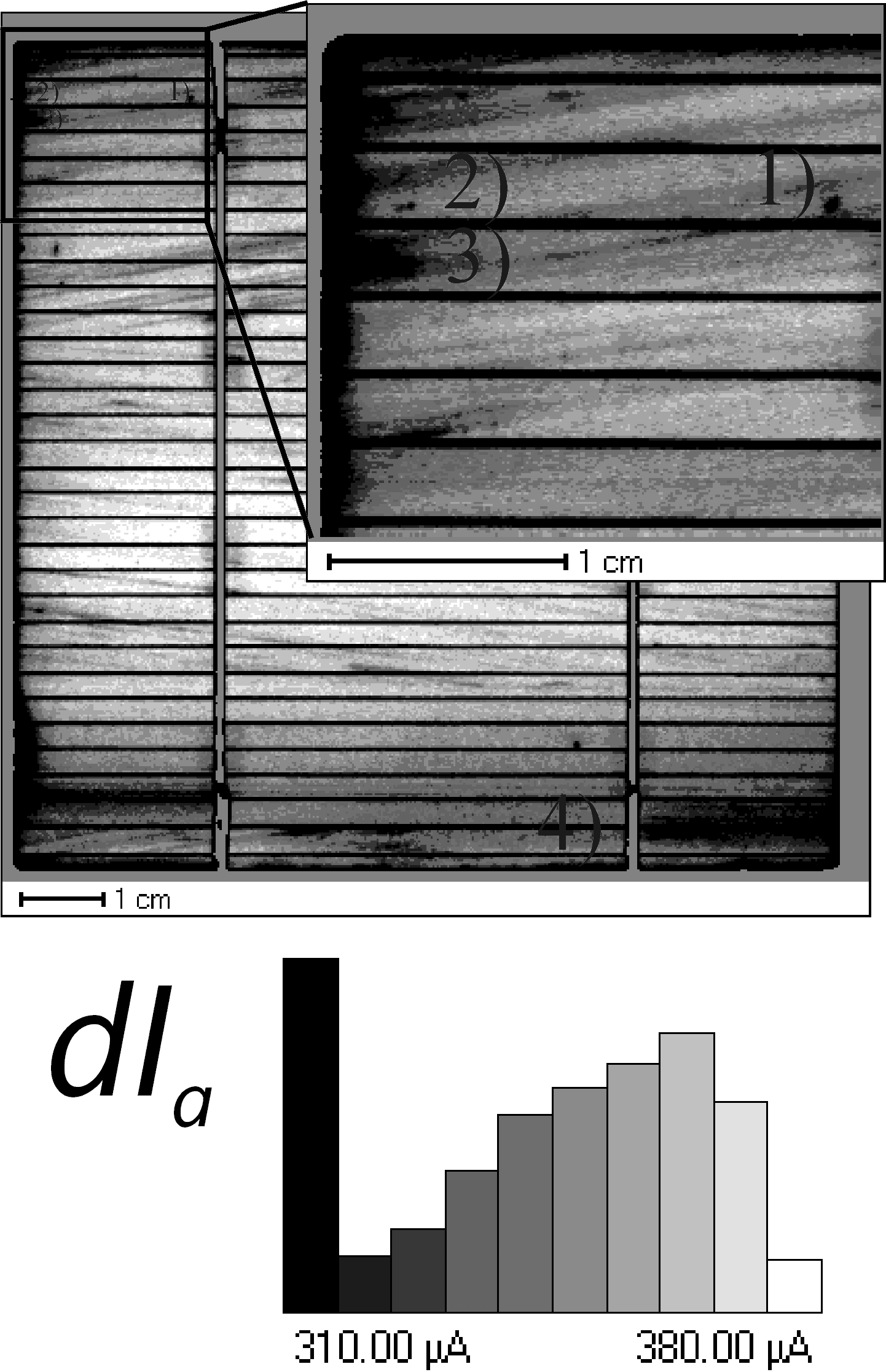
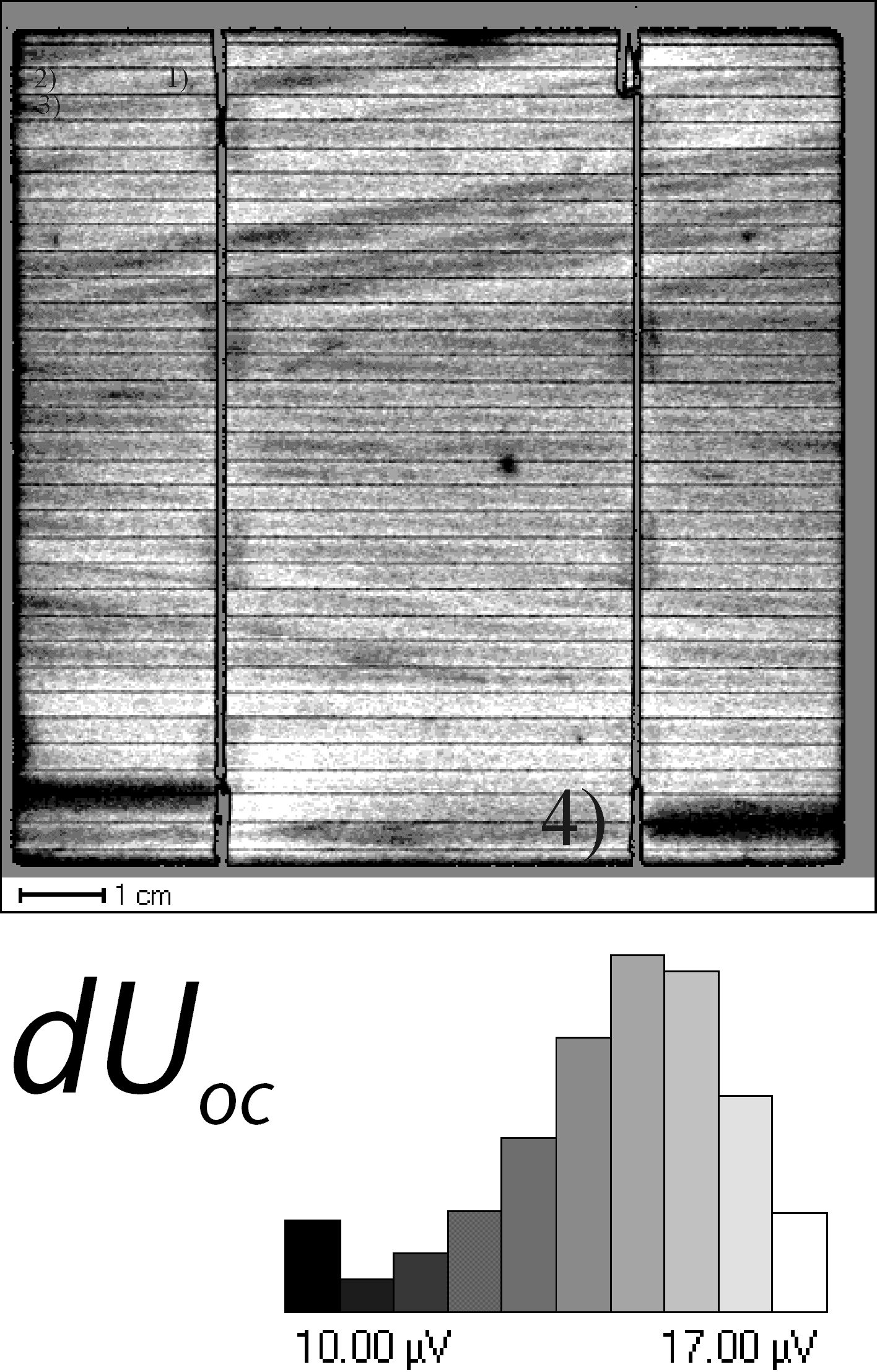
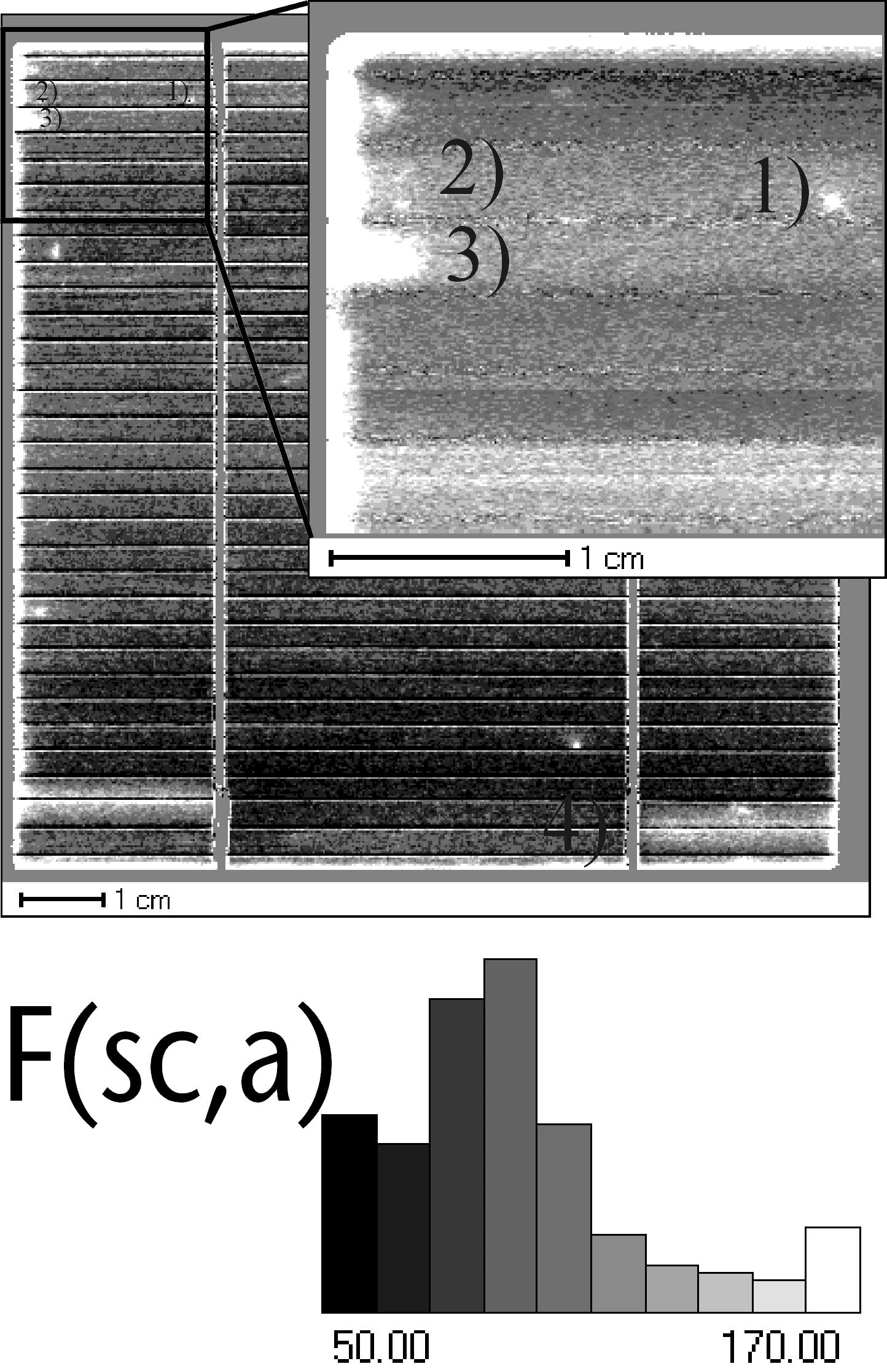
Figure 6: CELLO results for several points on the IV-curve of a solar cell: dIsc linear response of current at short circuit condition (LBIC); dIa linear response of current at optimal working point of solar cell; dUoc linear response of potential at open circuit condition; F(sc,a) plot of the "ratio" of dIsc and dIa according to Eq. (7). Insets: Enlarged maps of the upper left part of the solar cell.
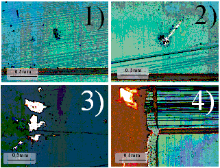
Figure 7: Optical microscope images of four defects indicated in Fig. 6. 1), 2) scratches through the pn-junction; 3) particles affecting the pn-junction and the AR-coating; 4) grid finger not connected to the main grid.
5. CONCLUSIONS
First results demonstrate that CELLO is a universal method for detecting and characterizing local defects in all solar cells since it is not restricted to silicon or crystalline materials. Including CELLO results into a detailed simulation program for solar cells should provide a powerful tool for improving the efficiency of solar cells since this would allow to systematically optimize the technology for particular materials and processes.
REFERENCES