 |
Franks formula relates the sum
d of all Burgers vectors cut by a vector r (which
is required to be in the plane of the boundary) to the (small) rotation angle
a around an arbitrary polar vector
l that generates the second crystal from the first one. It
reads: |
|
 |
|
 |
Franks formula at this point is a continuity
equation, it gives a value of d for every a and r |
|
 |
Burgers vectors, however, are discrete. This
requires the vector d to be discrete, too. |
|
 |
Since Burgers vectors are translation vectors of
the lattice, d can only be a sum of Burgers vectors if
l is a lattice vector so that the
"b-plane", the plane perpendicular to l
that contains the possible Burgers vectors, is a lattice plane, too (i.e. can
be indexed with {hkl}, with h, k, l = integers). It contains lattice points
that define the possible Burgers vectors in this plane. |
|
 |
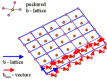
Note that the Burgers vectors defined in this way
must not necessarily be the shortest possible Burgers vectors
bmin, i.e. the Burgers vectors of real dislocations.
It is, however, always possible to decompose the b vectors of the
-lattice into, e.g., a/2<110> type Burgers vectors of the fcc
lattice. This may require bmin-vectors that are not
contained in the b- plane - but all we have to do then is to
imagine the b-plane to be "puckered" as shown
below. |
|
|
 |
 |
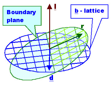
On the plane of the boundary, an arbitrary
r would intersect the projection of the b-lattice
onto the boundary plane along the l-direction . In a schematic
view we have the following situation: |
|
|
 |
 |
Franks formula can now be understood as a discrete
imaging of points in a two-dimensional "Burgers vector space" onto a
plane in real space. |
|
 |
The Burgers vector count along r (after
translating it to smallest possible vectors bmin)
gives the number of dislocations that are found if going along r
in the boundary plane. If even spacing is assumed, we also know the spacing in
the particular direction given by r. |
|
 |
The line direction of the dislocation is obtained by probing
the whole two-dimensional grain boundary space by sweeping r
around. What happens then can be understood in purely geometrical terms, as we
will see. |
 |
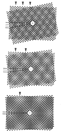
First of all it is important to
realize that the b-lattice is simply the Moirée pattern of the superimposed two
crystals obtained by rotating the {hkl} planes perpendicular to l
on top of each other by a as shown below for
three different as with a picture from
Bollmanns book. |
|
|
 |
|
 |
In the whitish (bright) areas, there is a high degree of
coincidence of lattice points, whereas in the black areas the misfit is
largest. Whenever a vector from the origin crosses a black area to reach a
whitish area again, the translation relative to a equivalent vector in the
other lattice is just a lattice vector of the underlying plane, which is the
b-plane in our definition. |
|
|
|
 |
If the crystal now introduces a boundary, it will increase the
whitish areas, the areas of best fit, and concentrate the misfit on the black
areas, which correspond to the dislocations. |
|
|
|
 |
Since the does not depend on its position along
l (in other words: Which planes of the real crystals
perpendicular to l we rotate relative to each other does not
matter), we can extend it along the l direction. If we enclose
the lattice points of the b-lattice in
Wigner-Seitz cells, we obtain a kind of
honeycomb structure. |
 |
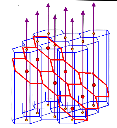
The decisive point now is that the boundary plane,
which can have any position possible relative to l, intersects
this "honeycomb" b-lattice somehow, for an cases we
obtain the following picture (again taken from Bollmanns book): |
| |
|
 |
|
 |
The b-lattice consists of the yellow lattice
points. It is turned into the three-dimensional "honeycomb" lattice
by introducing Wigner-Seitz cells (blue lines) and continuing it along the
l direction (magenta arrows). |
| |
|
|
 |
An inclined boundary plane will have a dislocation wherever
the boundary plan intersects the honeycombs. The resulting dislocation network
is shown with red lines. The points of best fit Red points) are in the center
of the network as it must be. |
 |
The final interpretation now is as follows: |
|
 |
Wherever the boundary plane intersects a cell wall
of the (three-dimensional) b-lattice, we have a dislocation with
the Burgers vector as defined by the b-lattice. The lines defined
by the intersection of the boundary plane and the cell walls then directly
define the dislocation lines - we get a direct rendering of the dislocation
network in the boundary. |
|
 |
Of course, the geometry of the dislocation network
obtained in this way depends on the kind of unit cell we chose for the
"honeycomb" b-lattice. Wigner-Seitz cells, while
universal, may not be best choice possible. But it is always possiblenow to
"develop" the network obtained in a network with minimum energy by
using the rules of dislocation interaction as in the
example with the small angle twist
boundary on a {111} plane. |
 |
These and other complications need more
considerations. However, remembering that Franks formula is an approximation
and covers only small angle grain boundaries, it is not worth the effort to
improve this limited theory. It is a better at this point approach to unleash
the full power of O-lattice theory which
contains franks formula as a special case. |


