 |
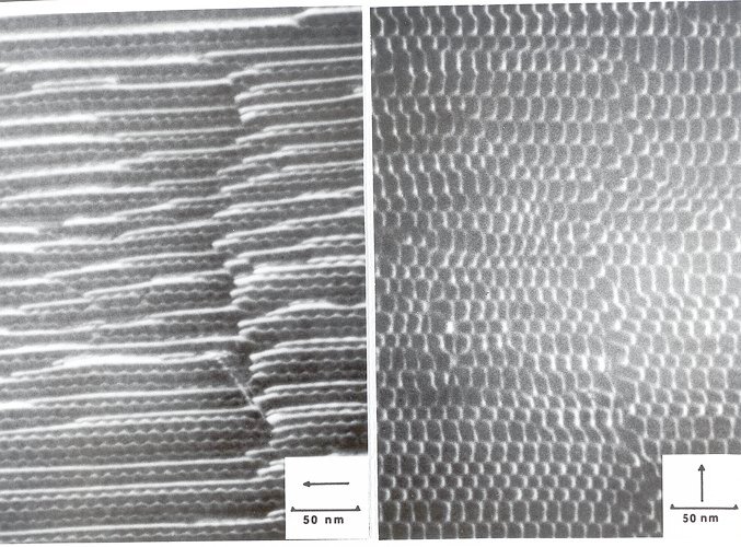
On the right-hand side is the (full-size) picture
from the backbone, on the left-hand side the same area is shown, but imaged with
different weak-beam conditions. |
|
 |
It can be seen that a whole new set of dislocations lights up. They are edge dislocations
accounting for a fairly large degree of (unintended) tilt in this grain boundary. They interact with the screw dislocations
visible on the right hand side to form a fairly complicated network of grain-boundary dislocations. |
|
 |
The big distortion in the edge dislocation structure running from top to bottom in the right-hand side
of the image is probably due to a change of the grain boundary plane: All dislocations must move "up" or "down":
the structure changes. |
| |
|
|
 |
This is another good example of the power of contrast analysis with TEM and the difficulties of
extracting the information contained in the picture (just try to draw the network with all the Burgers vectors indicated). |
| | |
© H. Föll (Defects - Script)

![]() 7.2.2 Case Studies: Small Angle Grain Boundaries in Silicon I
7.2.2 Case Studies: Small Angle Grain Boundaries in Silicon I