| |
 |
Lets consider a solar cell as an ideal pn-junction, for simplicities sake even without
the current contributions from the space charge region, but with a built in series resistance
Rser and a shunt resistance
Rshunt |
|
 |
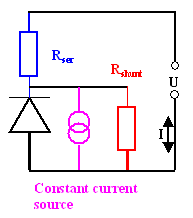
We have the following equivalent circuit diagram (also defining what is meant by a shunt resistance). See
also the "Solar Cell Primer" in a basic module |
| | |
| |
|  |
The shunt resistance takes into account that the huge area of the pn-junction of a solar cell might have weak
points (locally, e.g. at the edge) which short-circuit the junction somewhat. These defects are summarily described by a
shunt resistor. |
 |
The constant current source mimics the current generated in the junction by light. it simply defines a current value
Iphot (not to be mixed up with the terminal current I) that is given by the light
and added (with a negative sign) to the junction current, i.e. Ijunct = Idiode(U)
– Iphot
. Iphot thus simply moves the total characteristics of the diode downwards on the current scale. |
| | |
|
 |
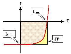
Take the following schematic curve of I-U-characteristics as a reference and for the
definition of the following terms |
| |
|
| |
|  |
The fill factor is the relation between the area of the yellow rectangle to the pinkish area under the characteristics. |
| | |
 |
Derive the complete current-voltage relationship. |
 |
Discuss qualitatively the influence of the two resistors with particular respect to: |
|
 |
The open-circuit voltage UOC |
|
 |
the short-circuit current ISC |
|
 |
The fill factor FF (the degree of "rectangularism" of the characteristics). |
|
 |
The efficiency h which is proportional to UOC,
ISC , and FF, i.e. |
|
| |
| |
| h | = |
const · UOC · ISC · FF |
|
|
| | |
| | |
 |
Link to several exercises to solar cells, far exceeding this one, with the solutions. There, look at chapter 8. |
| |
© H. Föll (Semiconductors - Script)

