CRYSTAL ORIENTATION AND ELECTROLYTE DEPENDENCE FOR
MACROPORE NUCLEATION AND STABLE GROWTH ON P-TYPE-SI
M. Christophersen, J. Carstensen, A. Feuerhake, and H.
Föll
Faculty of Engineering, University of Kiel, Kaiserstr. 2,
24143 Kiel, Germany
Macropore formation in moderately doped
p-type-silicon was studied in mostly galvanostatic experiments (2 – 10
mA/cm2) with various fluoride containing electrolytes and substrate
orientations [(100), (511), ![]() ,
(111)] from the nucleation phase to the phase of stable pore growth. Macropores
on p-type-silicon always grow anisotropically in <100>- and
<113>-directions. The most important parameter of the electrolyte is its
ability to supply oxygen and hydrogen. Whereas oxygen is necessary for
smoothing the pore tips, hydrogen is the decisive factor for the anisotropic
growth and the passivation of macropore side walls. Based on a better
theoretical understanding of the electrode processes in general pore formation
in particular, etching conditions could be optimized for the generation of
macropores in p-type-silicon with better aspect ratios, better stability, and
smaller diameters than those in n-type si licon.
,
(111)] from the nucleation phase to the phase of stable pore growth. Macropores
on p-type-silicon always grow anisotropically in <100>- and
<113>-directions. The most important parameter of the electrolyte is its
ability to supply oxygen and hydrogen. Whereas oxygen is necessary for
smoothing the pore tips, hydrogen is the decisive factor for the anisotropic
growth and the passivation of macropore side walls. Based on a better
theoretical understanding of the electrode processes in general pore formation
in particular, etching conditions could be optimized for the generation of
macropores in p-type-silicon with better aspect ratios, better stability, and
smaller diameters than those in n-type si licon.
p-Si macropores, anisotropic pore growth, organic electrolytes, pore nucleation, H-termination, anodic oxide formation
In 1990 Lehmann and Föll [1, 2] discovered that very regular arrays of macropores with extremely large aspect ratios could be obtained in the n-Si/HF system. They explained the formation of these pores on the base of a so-called "space charge region" model. Within this model some quantitative
|
|
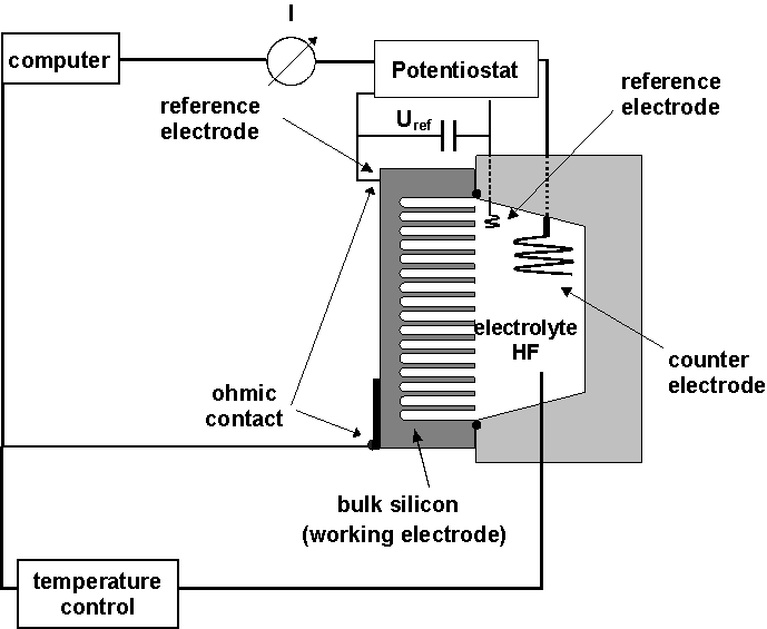
| Fig. 1: Schematic illustration of the etching cell. |
prediction could be made [3], which were used for the control of involved etching procedures yielding, among other results, the first photonic crystals with bandgaps in the infrared region [4, 5].
Certain limitations of the etching process, which could not be accounted for by this model [6], but especially the discovery of macropores in p-type Si [7 - 10] (which, according to the space charge region model, should not occur), made clear, however, that space charge region effects are not the only decisive factor for the formation of macropores. In a more comprehensive view, pore formation can now be seen as belonging to the class of "critical phenomena", and space charge region effects are but one of several mechanisms that tend to synchronize current flow in time and space and thus induce current oscillations and pore formation [11]. In [12, 13] it is outlined that the oscillations in the Si-HF system are based on a synchronization of localized current bursts in time; in [11, 14, 18] a first attempt is made to understand pore etching and general electrode processes as a synchronization of current bursts in space. In essence, a complete model for the whole I-V- curve of the Si-HF-system seems to be possible. The investigation reported in this paper were partially guided by the insights cited above; to some extent they supplied data for the formulation of the "current burst model".
Whereas it was first believed that macropores in Si were restricted to rather peculiar electrolytes (especially water-free Acetonitrile) and Si with a high-resistivity [7], it was later discovered that many electrolytes are suitable [8, 9] (including diluted HF [10]), and that the doping is no more decisive than in n-type Si. The variability of pores with respect to their shape, length, filling with nano- or mesopores, etc. [cf. 15], is, however, larger than in n-type Si; this is partially due to the range of (organic) electrolytes used.
In this investigation we firstly aim for a better understanding of the pore formation process; in the relevant experiments we use a new general theory of pore formation (outlined in [11]) as a guideline. Secondly, based on the results, we try to find a set of optimized parameters for the formation of well-defined macropores with high aspect ratios and typical dimension below 1 µm on p-type Si. The major parameter for achieving this goal is the proper choice of the electrolyte. From theory, we took as major variables the HF – concentration, the supply of oxygen to the interface (which should be rather restricted) and the supply of reactive H (which should be large). Furthermore, the conductivity of the electrolyte, the viscosity and the stability of its components were taken into account.
In addition to electrolytes mentioned in the literature, e.g. Acetonitrile (MeCN) [7], Diemethylforamide (DMF) [8], and, as a speciality, diluted HF without organic agents [10], we used Diemethylsulfoxide (DMSO), Tetraethylensilicate (TEOS), and especially mixtures of these electrolytes with Water (supplying O and H, as outlined in [16, 17]) and Diethyleneglycol (DG) supplying only H.
Pore formation was investigated including the nucleation and reorganization processes which usually precede stable pore growth.
Besides standard preparation techniques for REM investigations of pore-size, -depth, shape,-orientation and filling with mesopores, TEM investigation were performed; the results are reported in [18]. In most experiments, the valence n of the etching process was also measured via the mass loss (D m) according to the formula
![]() (1)
(1)
with I = etching current, t = etching
time, Ar = (28,08 g/mol) and Na
= (![]() mol-1).
mol-1).
A schematic view of the etching set-up is shown in Fig. 1; note that reference electrodes and temperature control is essential for reproducible results.
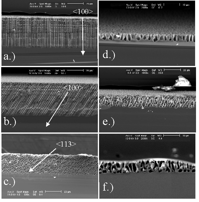
In all experiments pores always grew either in <100> or <113> directions in accordance with the results reported for macropores in n-type Si in [19]; examples are shown in Fig. 2. There is, however, a large variability in the appearance of pores lying in these preferred directions ranging from extremely straight pores with rather constant diameters (cf. Fig. 2a - c) to very wavy and "bad" pores with constantly changing diameters (cf. Fig. 2d - f). The bad pores are specifically observed in the HF/H2O systems, or more generally, in all etching systems with relatively large amounts of available oxygen – usually supplied by the water in the system. Extremely straight – in short "good" macropores – are obtained in systems with reduced O and increased H availability for the interface reactions. This leads to the conclusion - in perfect agreement with [11] - that the oxidation process is isotropic and that the process of H – termination of the inter face is anisotropic – it is fastest on {111} and slowest on {100} [20]. In [11] we reason that the reaction of "dangling bonds" with H tends to passivate the surface, and that the degree of H – termination of a given surface influences the nucleation probability of current paths through the interface and thus the local dissolution of Si.
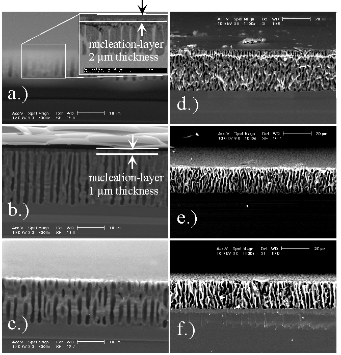
The relative role of O and H was investigated in the MeCN system with the addition of H2O (supplying both H and O ) and DG (supplying only H); representative results are shown in Fig. 3. Most prominent is the observation that pores in pure MeCN (containing only the unavoidable amount of H2O introduced by the HF which is never totally water free) are always filled with mesoporous Si (Fig. 3a, d); that it is indeed mesoporous Si is shown by the TEM investigation reported in [18]) whereas for the oxygen containing electrolytes the pores are not filled. The addition of DG tends to keep the pores filled; a small amount of oxygen, however, which cannot always be prevented, removes the filling. As can be seen in Fig. 3 (backed by independent measurements with a Dektak profilometer), the nucleation process always leaves a layer of mesoporous Si for pure MeCN. Pores from the electrolyte mixtures, however, were free of filling.
|
|
|
Fig. 2: Macropore-formation on p-type-silicon is anisotropic in <100> and <113>-direction. Organic electrolytes especially DMSO are beneficial for pore-formation. The anisotropy is strongly enhanced by reducing the oxidizing species. a) DMSO (100) n = 2.1 crater-depth 0.62 µm; b) DMSO (55 12) n = 2.1 crater-depth 0.75 µm; c) DMSO (111) n = 2.05 crater-depth 0.9 µm; d) H2O (100) n = 1.9; e) H2O (55 12) n=1.5; f) H2O (111) n = 1.5. |
They did not show a mesoporous nucleation layer either, instead a "crater", i.e. a depression below the original surface was formed to a depth of a few µm. We conclude that the presence of H enables easier nucleation, increases the pore length, and generally makes for better pores.
|
|
| Fig. 3 (For details see text): a) MeCN (100) n = 4, nucleation-layer-thickness: 2 µm; 3b) MeCN+DG (100) n = 2.5, nucleation-layer-thickness: 1 µm, 3c) MeCN+H2O (100) n = 3, no nucleation-layer; 3d) MeCN (111) n = 3.5; 3e) MeCN+DG (111) n = 2.25; 3f) MeCN+H2O (111) n = 1.8 |
The presence of O removes pore fillings (3c) and nucleation layers and results in a crater-formation instead. The hydrogen supplied by the water addition also enhances the pore length (3c). Figs. 3d-f, however, show neither a nucleation-layer nor a crater, which is most likely due to the usage of lapped instead of polished wafers in this case. Oxygen, on the other side, influences the diameters of the macropores and smoothes the pores.
|
|
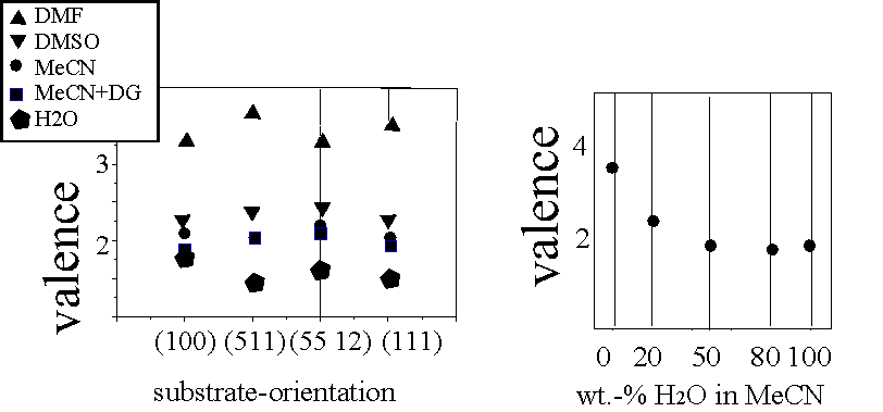
| Fig. 4: The valence is not a function of the substrate-orientation, but a strong function of the water-concentration in the electrolyte (H2O in MeCN) and the electrolyte itself. |
An additional feature of interest is the valence n of the reactions. It depends on all parameters but seems to respond most to the H – availability. Systematic investigations of the valence as a function of electrolyte systems and crystal orientation demonstrate that the substrate orientation is of little influence whereas the electrolyte system and the H2O concentration is decisive (Fig. 4).
The experiments, together with general insights [7, 8, 10, 11], give clear guidelines for the design of optimized pore etching conditions. Besides an optimization of conductivity, viscosity, and temperature (which do not directly influence the interface reactions but are nonetheless important), electrolyte optimization calls for
- Optimized H-termination: This defines the anisotropy of the pore growth and suppresses the nucleation of side pores, i.e. it decreases the fuzziness of pores. It generally tends to nucleate new current paths (which, according to [11] occur in bursts) in areas where current flow took place not too long ago – otherwise the surface will be passivated by the process of H – termination.
- Some, but not too much oxidation is needed to clear the pores of mesoporous Si and to ensure round cross sections by adding some isotropy after direct (and very anisotropic direct dissolution) has cleared the terrain.
- Relatively large current densities. This requires many current bursts per time unit and thus does not allow too much time for the passivation process of H – termination (which would otherwise introduce too much stochastic elements in the nucleation of new current bursts).
- Standard Si doping (6- 10 Wcm) if sub-µm pores are desired.
|
|
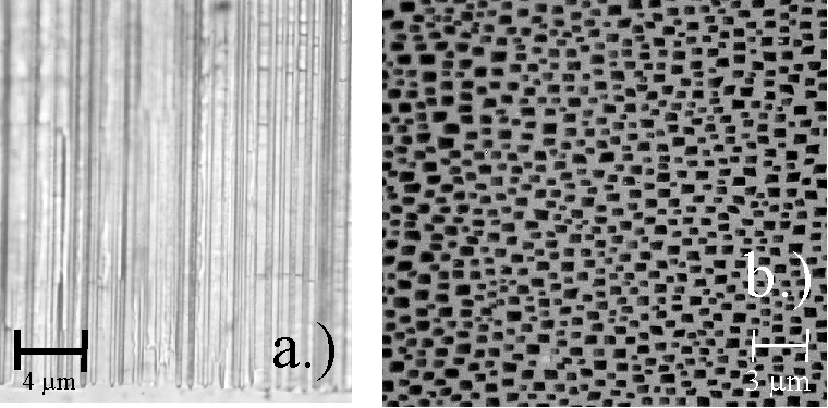
| Fig. 5 (Optical micrograph): Stable macropores of very good quality can be formed in p-type-silicon with optimized electrolytes (5a, (110)-plane view ) and a sub-µm geometry is principally possible (6b, (100)-plane view; pore-diameters: 700nm – 1 µm). |
|
|
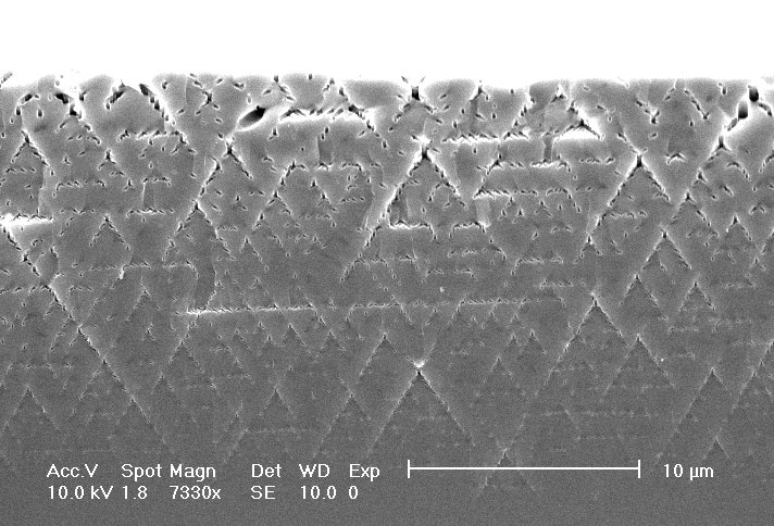
| Fig. 6: First three dimensional photonic crystal obtained in n-type Si following an optimization process. |
Following these guidelines a first optimized process uses DMSO or DMF with 4 weight-% H2O and a controlled current density around 10 mA/cm2.The result is shown in Fig. 5. Very straight and generally "good" pores nucleated at random, with rectangular to square cross sections and mean diameters from 700 nm to 1.2 µm were obtained. Knowing the time constants of the processes at the interface allows even variations of the current on a smaller time scale without influencing the pore geometry. In the example of Fig. 5, a (sinus) variation of the current between 7 – 10 mA/cm2 had no visible influence on the pore geometry. A second optimized process, which modified electrolytes and a time-dependent value of the current, allows to obtain pores with the same quality and pore length of 400 µm and beyond.
Finally, combining optimized etching conditions with the peculiar orientation dependence of macropores and the observation that pore arrays induced by lithographically defined nuclei are stable even at geometries deviating somewhat from their preferred arrangement, three dimensional photonic crystals should be possible in the sub-µm range. The first example of a three dimensional photonic crystal obtained in this way for n-type Si (and thus limited to dimensions > 1 µm) is shown in Fig. 6.
This work was supported by the Deutsche Forschungsgemeinschaft. We are indebted to Wacker Chemitronic for supplying bulk Si needed to cut samples with unusual orientations and to our colleagues from the MPI-MSP Halle for experimental support and fruitful discussions.
[2] H. Föll, Appl. Phys. A, 53, (1991) 8
[3] V. Lehmann, Thin Solid Film 255, (1995) 1
[4] U. Grüning, S. Ottow, V. Lehmann, Appl. Phys. Lett., 68, (1996)747
[5] F. Müller, A. Birner, U. Gösele, V. Lehmann, S. Ottow, H. Föll, PSST (Int. Conf. Porous Si Science and Technology) Proceedings, (1998) in press
[6] M. H. Al Rifai, M. Christophersen, S. Ottow, H. Föll, PSST (Int. Conf. Porous Si Science and Technology) Proceedings, (1998) in press
[7] E. K. Propst, P.A. Kohl, J. Electrochem. Soc., 141, (1994) 1006
[8] E. A. Ponomarev, C. Levý-Clement, J. Electrochem. Soc. Lett., 1, (1998) 1002
[9] R. B. Wehrspohn, J.N. Chazalviel, F. Ozanam, J. Electrochem. Soc., 145, (1998) 2958
[10] V. Lehmann, S. Rönnebeck, J. Electrochem. Soc., submitted
[11] J. Carstensen, M. Christophersen, H. Föll, this proceedings
[12] J. Carstensen, R. Prange, G. S. Popkirov, H. Föll, Appl. Phys. A 67, (1998) 459
[13] J. Carstensen, R. Prange, H. Föll, J. Electrochem. Soc., 146, (1999) 1134
[14] G. Hasse, J. Carstensen, H. Föll, this proceedings
[15] R. L. Smith, S. D. Collins, J. Appl. Phys., 71, (1992) R1
[16] P. Allongue, C. Henry de Villeneuve, L. Pinsard, M. C. Bernard, Appl. Phys. Lett. 67, (1995) 7
[17] M. C. dos Santos, O. Teschke, J. Vac. Sci. Technol. B, 16, (1998) 2105
[18] C. Jäger, B. Finkenberger, W. Jäger, M. Christophersen, J. Carstensen, H. Föll, this proceedings
[19] S. Rönnebeck, J. Carstensen, S. Ottow, H. Föll, Electrochemical and Solid-State Lett., 2 (3), (1999) 126
[20] K. W. Kolasinski, Int. J. Mod. Phys., B9, (1995) 2753
