Theopore
PORE FORMATION MECHANISMS FOR THE SI-HF SYSTEM
J. Carstensen, M. Christophersen, and H.
Föll
Faculty of Engineering, University of Kiel, Kaiserstr. 2,
24143 Kiel, Germany
A model is presented with the potential to account for all processes of the reactive Si – liquid interface including, e.g., current oscillations, and the formation of nano-, meso, and macropores with their specific dependence on crystal orientation. The model assumes that current flow is spatially and temporally inhomogeneous - current thus flows in current "lines" occurring in current "bursts". The mean cycle time between correlated current bursts is mostly given by the kinetics of oxide dissolution and hydrogen passivation (which introduces a strong surface orientation dependence). Structure generation at the Si electrode (current oscillations in the time domain or pore formation in the space domain) under these assumptions is a self-organized process resulting from an interplay of synchronizing and desynchronizing mechanisms. Synchronizing mechanisms always couple the nucleation of a new current burst in a specific area to the history of that area, desynchronizin g mechanisms may also depend on the interaction of current burst. Examples for synchronizing mechanisms are enhanced nucleation probabilities on (100) surfaces, response to local oxides from another current burst, or coupling of current bursts by space charge region effects. Desynchronisation results, e.g., from quantum wire effects, or local reduction of reactants or potential by a current line. The model accounts qualitatively for most if not all observed phenomena, gives a number of quantitative relations, and makes numerous predictions.
Silicon electrochemistry, Self-organized processes, Pore Nucleation, Pore Formation, H-Termination, p-Si macropores.
The solid – liquid junction of Silicon and F- – containing liquids exhibits a number of peculiar features, e.g. a very low density of interface states, i.e. a "passivated" interface [1]. If the junction is biased, the IV – characteristic in diluted HF is quite complicated and exhibits two current peaks and strong current- or voltage oscillations at large current densities (for reviews see [2, 3]). Perhaps the most outstanding features are the many different kinds of pores – nanopores, mesopores, macropores and so on - that form under a wide range of conditions in many electrolytes, including organic substances [4, 5]. Despite intensive research triggered by the finding that nanoporous Si shows strong luminescence [6, 7], neither the intricacies of the IV – characteristic nor the processes responsible for the formation of pores, including their rather peculiar dependence on crystal orientation, are well understood. Whereas mechanisms for some aspects of pore formation have been proposed [8-16], they are generally restricted to one kind of pores and possess very little predictive power.
This paper attempts for the first time to give a coherent theory for all phenomena encountered at the Si – liquid interface subjected to current flow, including all aspects of pore formation and seemingly unrelated issues as, e.g., the current or voltage oscillations. In what follows, we first discuss the premises of the model, illustrate their interaction on the subject of macropores in p-type Si, generalize the model for all aspects concerning the electrochemistry of Silicon, and finally give some examples of its explanatory and predictive power. Of course, given the space restriction, this survey will only touch the major points and omit details.
In [17, 18] the first model capable of explaining the current/voltage oscillations in Si was given. Its key feature was the postulation of a spatially and temporally inhomogeneous current flow. In short, local current flow starts whenever the local field strength is high enough, generates some oxide and stops. The oxide is dissolved purely chemically; whenever it is thin enough, the cycle starts anew. This cyclic process contains several statistical elements, in particular the probability for current "nucleation" and "quenching" as a function of the field strength and thus the local oxide thickness. These "local oscillators" generally run with random phases (producing a constant macroscopic current), but under certain conditions a percolation process may lead to a partial temporal synchronization and thus to macroscopic current oscillations.
|
|
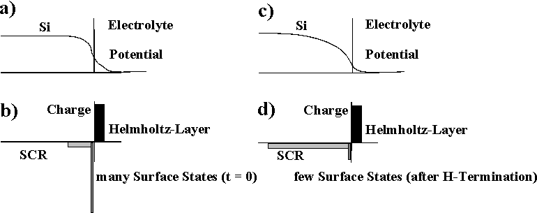
| Fig. 1: With many surface states the major potential drop occurs in the Helmholtz layer of the electrolyte (a), (b), driving the electrochemical reactions. With few surface states a space charge region consumes most of the applied potential and thus effectively passivates the surface (c), (d). |
|
|
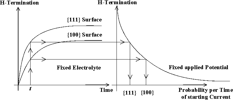
| Fig. 2: Time constant and perfection of H-termination differ strongly for (100) and (111) surface orientation. This leads to an increased probability of local current nucleation on (100) surfaces. |
We propose that pore nucleation and growth follow similar concepts. Thus the fundamental assumptions for all processes at the Si – liquid interface are:
- Current flow is always spatially and temporally inhomogeneous, i.e. it occurs in local current "bursts". This means that at any given "point" (= area increment) on the interface the current state is either "on" or "off". The state changes with a characteristic mean time constant, which depends on the pertaining set of external parameters, e.g. the applied potential, the F- concentration, the temperature, the type and doping of the Si, etc.
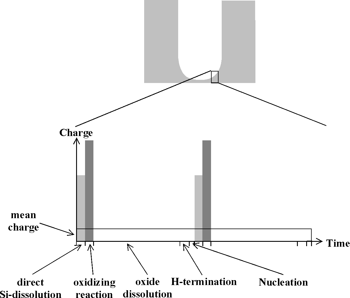
- Current flow either induces direct Si dissolution (charge consumption: QS, time consumption TS) or oxidation (QOx, TOx); the oxidation process, if occurring, always follows or is triggered by a direct dissolution process. Direct Si dissolution has a valence between 1 and 4 (depending on the availability of holes) and is strongly localized, generating a nanometer sized pore or a cluster of nanopores. If in a second step this area is oxidized (with a valence of 4), this process has a lateral spread of a few nanometers because the current line tries to avoid the freshly formed oxide.
- Oxide formed during a current burst always dissolves purely chemically (releasing a (small) charge QD [21]) with a time constant TD mainly determined by the chemistry and the temperature. The time needed for dissolving an oxide is generally much larger than the time needed for its production.
- Oxide free surfaces tend to be totally covered with strongly bonded hydrogen and then are passivated; i.e. they have few or no interface states. The process of complete hydrogenation takes an appreciable amount of time; the time constant and the perfection of this process depends strongly on the crystallographic orientation of the surface [1, 12, 19, 20]. The {100} surface needs the longest, the {111} surface the shortest time for complete coverage and thus passivation. As illustrated in Fig. 1, as long as the surface is not sufficiently covered with H, there is no appreciable space charge region within the Si because the surface states pin the Fermi level somewhere in midband. As a collateral, it will be difficult to nucleate a new current burst on a perfectly passivated surface, but if current flow is eventually initiated, the space charge region immediately is swept out of the Si in a region comparable to its depth and thus much larger than the current bearin g "point". The H-termination process is the major synchronizing force for self-organized structure formation because it correlates the nucleation for current bursts. TH is the time available for the H-termination before local current flow starts again.
- The nucleation of a new current burst in a given area starts a new cycle. It may depend on several parameters, paramount, however, is the degree of local H-passivation Since the H-passivation process works fastest on {111} surfaces, these surfaces show a strongly reduced probability for generating current bursts and thus for being etched; the opposite is true for {100} (and probably {113}) surfaces; this mechanism is illustrated in Fig. 2.
A sequence of the processes given above constitutes a complete cycle from "current on" via "current off" to "current on" again. The mean time for one complete cycle is given by the sum of the characteristic time constants of the basic processes and is dominated by the time constants of oxide dissolution and hydrogen passivation. It is important to note that the macroscopic current (being always an average over many microcycles) is given by the total charge passed during the current bursts divided by the total cycle time. In other words, the macroscopic current may have nothing to do with the current in the current bursts, because it depends on time constants of processes that do not involve current flow. It is given by
![]() (1)
(1)
So far we did not invoke pore formation at all, but established the basics of a model that claims validity for all circumstances of current flowing through a Si – liquid junction. In order to be more specific, we will now discuss the application of the model to the tips of growing macropores in p-type Si.
|
|
|
Fig. 3: Schematic diagram of the charge and time consuming reactions at the Si-electrolyte interface |
The discovery of macropores in p-type Si [4, 5, 21-23] shattered the "space charge region" model of Lehmann and Föll [10] which so far has been quite successful in modeling macropore growth in n-type Silicon. Whereas it was first believed that macropores in Si were restricted to rather peculiar electrolytes (especially water-free Acetonitrile) and Si with a high-resistivity, it was later discovered that many electrolytes are suitable [5, 21-23] (including diluted HF [24]) and that the doping is not decisive. However, as in n-type Si, highly doped p-type Si tends to develop mesopores, i.e. pores with spatial dimensions in the 10 nm region. The nucleation of macropores in p-type Si is sometimes difficult [22, 23], and in some electrolytes the macropores are filled with meso- or nanoporous Silicon. Moreover, the dependence of the major pore direction on crystal orientation may vary with the external conditions [25] and certain additions to the main electrolyte may also have pronounced effects [22, 23] on pore morphology. Modeling macropore formation in p-type Si thus is a formidable task; space will not permit to go into details. It should be mentioned, however, that some of the results reported in [21 – 23] were obtained based on predictions of the model and not by trial and error.
Imagine a macropore in p-type Si which, after some time needed for pore nucleation and pore reorganization [23] grows with a constant macroscopic growth rate (corresponding to a constant mean current density) in that [100] direction which is most steeply inclined with respect to the surface of the sample [25]. In accordance with our model, the growing tip comprises several thousand current lines undergoing local cycles as shown in Fig. 4.
We consider one cycle at one particular area increment at some arbitrary point at the pore tip. If we first discuss a system with a negligible oxidation reaction (i.e. QS >> QOx; e.g. with nearly water (= oxygen) free acetonitrile (MeCN)) the current burst, according to Fig. 3, leads mostly to the direct dissolution of Si, "damaging" the silicon down to a few nm below the surface. The process ends as soon as the field strength at the damage layer decreases (the layer quickly exhaust all reactants and acts as an isolator). The process may start again as soon as new reactants (including holes) have diffused into the area and nucleation of a new current burst occurs, always in competition with the hydrogenation process). This results in macropores filled with mesoporous Si (since no oxidation reaction removes the left over Si between the current lines) with a strong preferential growth direction oft both pore types in <100& gt;.
If an oxidation reaction can occur (e.g. in MeCN with some water, cf. [23]) it takes over the current (second current burst in Fig. 3) as a consequence of the now much higher potential at the site (the space charge region collapsed locally because the newly created Si surface is not yet passivated), the missing H-layer (which hinders oxidation more than direct dissolution) and the now reduced supply of holes. Oxidation is rather isotropic and smoothes the area; no filling with mesopores is observed. The oxidation current burst ends as soon as the locally grown oxide is impenetrable to current in analogy to the oscillation model [17, 18]. In this case, the process with a relatively large time constant is the dissolution of the oxide (depending mainly on HF concentration and temperature). After that process is finished, the hydrogenation process starts with time constants that are rather long and strongly dependent on the surface orientation. The probability of nuclea ting a new current burst at the chosen site now depends on the orientation of the Si surface and the time lag since the last oxide was removed; it is lower at sites close to the pore wall as compared to sites at the pore center (cf. Fig. 2).
Since both times of current flow are small compared to the oxide dissolution and hydrogenation times, according to Eqn. (1) the mean local current density Jlocal at the pore tips is given by
|
|
|
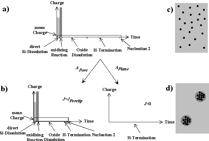
Fig. 4: Applying a global current density smaller than the average current density in a current burst will either require very long time constants to keep the mean charge passed in a burst small and to cover the surface completely with current lines (a), a statistical arrangement of current lines with the optimized (smaller) time constant of the system, leaving parts of the surface without current and creating nanopores (b, c), or induces a phase separation by rearranging the current lines in areas corresponding to macropores (d). |
![]() (2)
(2)
A first conclusion is that the global macroscopic current density, which also includes the areas without any current flow between the macropores, must be smaller that the mean local current density at the pore tip defined by Eqn. 1. Since TD is larger than TH and (Qs, + Qox)/TD is nearly constant and independent of the external current density [21], the mean diameters and distances of the pores are given by the ratio of the global current density to the mean current density in the local current bursts – which is the relation given in [26] for macropores in n-Si.
First, it is clear from the above that JPSL, the maximum current obtained at the so-called PSL peak in HF based electrolytes, is given by JPSL = max Jlocal = (QS + QOx)/TD and demands immediate nucleation of a new current burst as soon as the oxide has been dissolved (cf. Eqn. (2)). A necessary conclusion is that reactions at J = JPSL are dominated by oxide formation (especially dissolution) in contrast to e.g. [3] and in accordance with [21]. It is also clear that JPSL scales directly with the TD and thus the HF concentration [26]. Furthermore, no macropores will be observed because TH is small and thus the anisotropy of the H-termination, which is the major synchronizing force for macropore formation, cannot overcome the desynchronizing mechanisms.
Second, it is obvious that all considerations given above apply equally well to macropores in n-type Si with the added synchronizing mechanisms of backside illumination and overlapping space charge regions. Another mechanism may be illustrated with this example: Raising the voltage at a constant current density (easily done in n-type Si because the current is only given by the light intensity) reduces the hole consumption relative to what would be normal at that voltage at a flat surface (as shown in the IV-characteristics). The system, which tries to maintain the conditions expressed in its IV-characteristics, can only respond by reducing the hole-intensive oxidation reaction (valence = 4) and by increasing direct dissolution. On the whole, QS/QOx is increased, QOx/TD stays constant, and TH is somewhat decreased. Differences in nucleation probability on different surfaces increase – smaller, dendritic pores appear. In the extreme cases the system starts to generate additional holes by avalanche effects at small pore tips – "break-through" pores are prominent.
An inherent feature of the model is its applicability to the nucleation process of the macropores themselves (not to be confused with the nucleation of a current burst). The model only allows current flow in discrete current lines – i.e. there are at any given point in time areas where current flows and areas where no current flows. The mean global current therefore can always be written as
![]() . (3)
. (3)
As in similar situations, e.g. flux lines in superconductors, the system may choose a homogeneous (statistical) distribution of current lines, or arrange them in domains containing many current lines and domains with few or no current lines as illustrated in Fig. 4. Generally speaking, phase separations may occur depending on "coupling forces" which in our case express themselves as the synchronizing or desynchronizing mechanisms mentioned before, which consume time and charge.
If very few current lies are needed (at very low current densities), even small synchronizing forces eventually will lead to a phase separation. If the global current density now is raised, the system can only respond by lowering TH because TD is fixed. Nucleation then occurs very soon after the oxide has been dissolved and the influence of the surface anisotropy, which is also the major synchronizing force for macropore nucleation, is no longer strong enough – nanoporous Si layers, formed with appreciable QOx and with no preferential pore directions result. In the extreme case of TH = 0 (corresponding to J = JPSL), pores cease to exist and homogeneous dissolution of Si on a macroscopic scale takes place. This sequence explains the observed sequence or pores in the Si – HF system (macropores – nanopores – no pores; cf. [24]), when the current density is raised from very low values to JPSL.
For n-type Si illuminated form the backside, the current focussing process invoked earlier [10] may provide a synchronizing mechanism in addition to the H-passivation mechanism and thus helps in the nucleation of macropores by phase separation; systematic investigations of pore growth with n-type Si illuminated from the front side may help to distinguish between mechanisms.
H-termination now must be seen as the decisive synchronizing force not only for the stable growth of existing macropores, but also for the phase separation necessary for their very nucleation in n- and p-Si.
Mesopores, occurring in highly doped Si of both p- and n-type, seem to be anisotropic in [100] and are usually formed with a low valence approaching 1. They may now be understood as the result of a phase separation bundling only a few nanopores into one mesopore whenever the oxidation reaction is sufficiently suppressed. This happens whenever the supply of holes is much smaller than the "demand" at the interface. Since the potential at the interface increases with doping (space charge layers are small), the demand growth much faster than the supply (which, of course, also grows with doping). The system responds by suppressing the hole-intensive oxidation reaction and by supplying the necessary holes by chemical reactions (driving the valence to 1); the decisive time constant is now TH. Given time (and very little opportunity of oxidizing reactions), a second phase separation may finally produce the macropores filled with mesoporous Si observed in o rganic electrolytes with minimal water content.
[2] H. Föll, Appl. Phys. A, 53, (1991) 8
[3] R.L. Smith, S. D. Collins, J. Appl. Phys., 71, (1992) R1
[4] E. K. Propst, P.A. Kohl, J. Electrochem. Soc., 141, (1994) 1006
[5] E. A. Ponomarev, C. Levy-Clement, J. Electrochem. Soc. Lett., 1, (1998) 1002
[6] L. T. Canham, Appl. Phys. Lett., 57, (1990) 1046
[7] V. Lehmann, U. Gösele, Appl. Phys. Lett., 58, (1991) 856
[8] V. P. Parkhutik, V.I. Shershilsky, J. Phys. D, Appl. Phys., 25, (1992) 1258
[9] M. J. J. Theunissen, J. Electrochem. Soc., 119, (1972) 351 )
[10] V. Lehmann, H. Föll, J. Electrochem. Soc., 137, (1990) 653
[11] R. B. Wehrspohn, J.N. Chazalviel, F. Ozanam, J. Electrochem. Soc., 145, (1998) 2958
[12] M. C. dos Santos, O. Teschke, J. Vac. Sci. Technol. B, 16, (1998) 2105
[13] R. L. Smith, S. F. Chung, S.D. Collins, J. Electron. Matter., 17, (1988) 533
[14] Y. Kang, J. Jorne, J. Electrochem. Soc., 140, (1993) 2258
[15] A. Valance, Phys. Rev. B, 52, (1995) 8323
[16] X. G. Zhang, J. Electrochem. Soc., 138, (1991) 3750
[17] J. Carstensen, R. Prange, G.S. Popkirov, H. Föll, Appl. Phys. A 67, (1998) 459
[18] J. Carstensen, R. Prange, H. Föll, J. Electrochem. Soc., 146, (1999) 1134
[19] K. W. Kolasinski, Int. J. Mod. Phys., B9, (1995) 2753
[20] P. Allongue, C. Henry de Villeneuve, L. Pinsard, M.C. Bernard, Appl. Phys. Lett. 67, (1995) 7
[21] G. Hasse, J. Carstensen, H. Föll, this proceedings
[22] Ch. Jäger, B. Finkenberger, W. Jäger, M. Christophersen, J. Carstensen, H. Föll, this proceedings
[23] M. Christophersen, J. Carstensen, A. Feuerhake, H. Föll, this proceedings
[24] V. Lehmann, S. Rönnebeck, J. Electrochem. Soc., submitted
[25] S. Rönnebeck, J. Carstensen, S. Ottow, H. Föll, Electrochemical and Solid-State Lett., 2 (3), (1999) 126
[26] V. Lehmann, Thin Solid Film 255, (1995) 1


