PARAMETER DEPENDENCE OF PORE FORMATION IN SILICON
WITHIN A MODEL OF LOCAL CURRENT BURSTS
J. Carstensen, M. Christophersen, G. Hasse, and H. Föll
Materials Science, Faculty of Engineering
Kaiserstr. 2, 24143 Kiel, Germany
Phone: + 49 431 77572-507
Email: jc@tf.uni-kiel.de
The chemical reactions at the pore tip depend strongly on the choice of the electrolyte. They define the chemical transfer rate, properties and kinetics of the surface passivation, and ultimately the crystal orientation dependence of pore formation. In addition, there exist a number of processes which stabilize pore growth on length scales from several nm up to several 100 µm and determine, or at least influence, the size of pores: The potential distribution, carrier generation mechanisms and diffusion processes. We present a new model assuming a dissolution process which is inhomogeneous in time and in space (i.e. a local current burst). The time scales of the current bursts and the correlation length between this current bursts define additional time and length scales for the chemical dissolution processes at the silicon electrolyte interface which support or even overrule the length scales of the stabilizing processes listed above. This allows to design an electrolyte (using e.g. divers organic electrolytes and oxidizing and proton supplying ingredients) to optimize macropore growth in a wide range of materials and on length scales not possible in aqueous electrolytes.
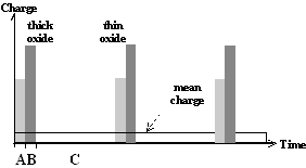
Starting point for the current burst model were investigations of current and voltage oscillations [1,2] in the anodic regime of the Si-HF system observed at high potentials, and especially the question how a process on a nm scale (thickness of oxide layer) can induce macroscopic oscillations on the complete surface of the sample i.e. on a cm scale. The answer to this problem was a macroscopic synchronization of local dissolution processes by (global) percolation which is induced by a local synchronization mechanism. For extremely diluted electrolytes the period of the oscillations was in the order of 100 sec, the time which is needed to dissolve the formerly generated oxide layer. The fundamental dissolution process on a nm scale has been named "current burst" since it consists of
This cycle is illustrated in Fig. 1a).
 |
 |
| a) |
b) |
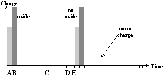
Fig. 1: Local current burst cycles for the dissolution of silicon. a) At high anodic bias current bursts nucleate through oxide. Starting with direct silicon dissolution (A) and oxide formation (B), the oxide has to be dissolved purely chemically (C). b) For low anodic bias the nucleation of current bursts starts on free surfaces with a direct dissolution of silicon (A) which can be followed by oxidizing (B). After oxide dissolution (C) the H-passivation of the free Si surface (D) starts. Overcoming this H-Termination (E), a new current burst cycle starts. |
|
The begin and end of each local current burst is
defined by an upper ![]() and
lower
and
lower ![]() critical value of
the local electric field strength which depends on the applied potential
U and the local oxide thickness s. The critical oxide layer
thickness' smin and
smax have been measured by transient current
analysis [2,3], showing that silicon oxide always growth through an existing
thin oxide layer and not on "free" silicon surfaces when applying
high anodic bias. The local synchronization of this current bursts is
postulated to be a (lateral) overlap of the oxide areas of current bursts. This
overlap increases with increasing potential since the lateral extension of
current bursts grows in proportion to the upper oxide thickness
smax and therefore increases with anodic bias. The
first manifestations of overlapping current bursts are domains of phase-coupled
current bursts. The domains grow in size with increasing potential, while the
oscillation frequency being the inverse of the dissolution cycle is reduced
proportionally to U. These effects have been studied by noise analysis
[3], showing that a monotonically growing noise amplitude (proportional to
domain size) with the correct frequency dependence is visible in the noise
spectra (even before the Iox-peak). Increasing the
bias reduces the noise and macroscopic oscillations occur (global overlap of
all domains) at the percolation point of the system. In the pore formation
regime such noise measurements were presented by Parkhutik [4].
critical value of
the local electric field strength which depends on the applied potential
U and the local oxide thickness s. The critical oxide layer
thickness' smin and
smax have been measured by transient current
analysis [2,3], showing that silicon oxide always growth through an existing
thin oxide layer and not on "free" silicon surfaces when applying
high anodic bias. The local synchronization of this current bursts is
postulated to be a (lateral) overlap of the oxide areas of current bursts. This
overlap increases with increasing potential since the lateral extension of
current bursts grows in proportion to the upper oxide thickness
smax and therefore increases with anodic bias. The
first manifestations of overlapping current bursts are domains of phase-coupled
current bursts. The domains grow in size with increasing potential, while the
oscillation frequency being the inverse of the dissolution cycle is reduced
proportionally to U. These effects have been studied by noise analysis
[3], showing that a monotonically growing noise amplitude (proportional to
domain size) with the correct frequency dependence is visible in the noise
spectra (even before the Iox-peak). Increasing the
bias reduces the noise and macroscopic oscillations occur (global overlap of
all domains) at the percolation point of the system. In the pore formation
regime such noise measurements were presented by Parkhutik [4].
This concept of a unique series of local silicon dissolution processes leading to different macroscopic processes along the IV-curve will be generalized to describe pore formation at lower anodic potentials as well; with one essential difference: Current bursts at low anodic bias nucleate on free silicon surfaces and not through a closed oxide layer. As illustrated in Fig. 1b) a hydrogen passivation of the free surfaces starts after the oxide has been dissolved. This H-passivation component, added to the current burst concept used for oscillations, is used to explain the strong crystal orientation dependence of macro- and mesopore formation. As illustrated in Fig. 2, the velocity as well as the perfection of H-passivation is highest on {111}-surfaces for all possible Si surfaces, whereas on {100} surfaces it has the lowest possible value since the number of dangling bonds which have to be passivated is significantly higher on {100} surfaces than on {111} surfaces. {100} surfaces will be preferentially dissolved [5], i.e. they are the preferred pore tips; {111}-surfaces are passivated most effectively, i.e. they are the preferred pore walls. On surfaces without any H-passivation, i.e. directly after a local oxide has been dissolved, the nucleation of a new current burst is most easy, i.e. right after a previous current burst comes to the end of its cycle.
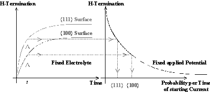 |
Fig. 2: The velocity as well as the perfection of H-passivation on {111}- and {100}- surfaces in HF containing electrolytes differs extremely (left side). Since a better H-termination is a good protection against nucleation of a new current burst, the {111}-surfaces are more stable (Þ preferentially pore walls) than {100}-surfaces (Þ preferentially pore tips) (right side). |
We just defined the interactions between current bursts in time (H-passivation) and in space (overlap). Both interactions depend strongly on the time needed for oxide dissolution: (i) only if a local oxide layer or "bump" is dissolved quickly enough, a significant time for H-passivation can expire before another current burst must nucleate; (ii). only if a locally generated oxide "bump" exists for a significant time, an interaction of two current bursts in space can occur. Since the time for dissolving oxide is extremely long (» sec) for a process on a nm scale, the correlation length between current bursts which defines the domain size as discussed above may be well in the µm range for pore formation and even in the cm range (for oscillations). Thus the time scale of the local current bursts defines simultaneously the lateral correlation length (domain size) between current bursts
Depending on the choice of parameters (potential, electrolyte, illumination,...), two different kinds of macroscopic phase separations can occur as a consequence of the interaction between current bursts: (i) The interaction in space (overlap) leads to a correlation of current bursts in time, i.e. a macroscopic phase separation in time between the phase of charge transfer and the phase of oxide dissolution; (ii) The interaction in time (degree of H-passivation) leads to a correlation of current bursts in space, i.e. for an externally defined over-all current density, some areas on the surface will be dissolved constantly (=pore tips), while other areas of the surface will be inert, increasing the H-termination even further as time goes by (=pore walls and remaining surface). This second kind of phase separation is just an abstract description for pore formation on the electrode surface.
Each current burst in Fig. 1b) consists of a series of charge (Qi) and time (ti) consuming processes. The processes which consume most charge are not identical with those who consume most time. Each local current burst carries a mean current iCB=å Qi / å ti which has a specific optimum value for a particular system. The average number NCB of current bursts on the silicon electrode for a constant external current I is given by I =NCB iCB. Since each current burst dissolves only a small area FB, the complete dissolved silicon surface area is FPore=NCB FCB which is the sum of the pore tip areas. At each pore tip we thus find the current density jCB = iCB / FCB, independent of the size of the pores, which, as a first result, explains the "Lehmann formula" [6]. If we increase the external current density up to J » jCB, the maximal current density under pore etching conditions is reached. This point on the IV curve is the PSL-peak, so we find JPSL » jCB.
To understand micro-, meso- and macropore formation, we have to explain how the local fixation of the current density to jB will simultaneously lead to the postulated phase separation. For that we will have a closer look on the processes of each current burst of Fig. 1b): (A) a direct dissolution of silicon occurs; (B) silicon may be oxidized; (C) the silicon oxide has to be dissolved purely chemically; (D) at the clean surface a (relatively slow) H-passivation starts; (E) To start the cycle again, each current burst has to overcome this H-passivation of the surface. Only in (A) and (B) charge is transferred, all processes need time. The current iCB = å Qi / å ti can be increased to its optimum value by maximizing the consumed charge å Qi, and/or minimizing the time needed, å ti. Since the pore nucleation is much easier on unpassivated surfaces, H-passivation is (i) a process which can increase iB by reducing the time between the beginning of H-passivation and pore nucleation, and (ii) a mechanism which leads to a preferential pore nucleation in areas where current bursts just stopped. This correlation in time between two subsequent current bursts is the driving force for the phase separation, i.e. the clustering of current bursts in some areas and thus to (meso and macro) pore formation.
Parameter Dependence of Pore Formation
In the current burst cycle of Fig. 1b) the processes (B) to (C) are strongly influenced by changing the oxygen concentration in the electrolyte and the processes (A), (D) and (E) by the concentration of hydrogen. This dependence on the chemical composition of the electrolyte allows to control the local current density jB as well as the driving force for the phase separation. In addition and of prime importance, the oxidizing component defines an intrinsic length scale by the size of domains and a time scale which depends on the time for dissolving oxide (strong dependence on HF-concentration). This time scale must be comparable to the time scale for the H-passivation; otherwise no selectivity between {100}- and {111} surfaces will exist which is essential for stable pore growth.
This intrinsic time and length scales are in competition to several additional stabilizing processes: The Poisson equation defines the potential distribution across space charge region (SCR) and Helmholtz layers (HL) (µm scale). Quantum confinement [7] and carrier generation by temperature,
light, and avalanche break-through [8] define the number of holes available for the chemical reactions (nm to µm scale), whereas diffusion processes define the transport of holes and reactants to and from the reaction layer (up to cm scale).
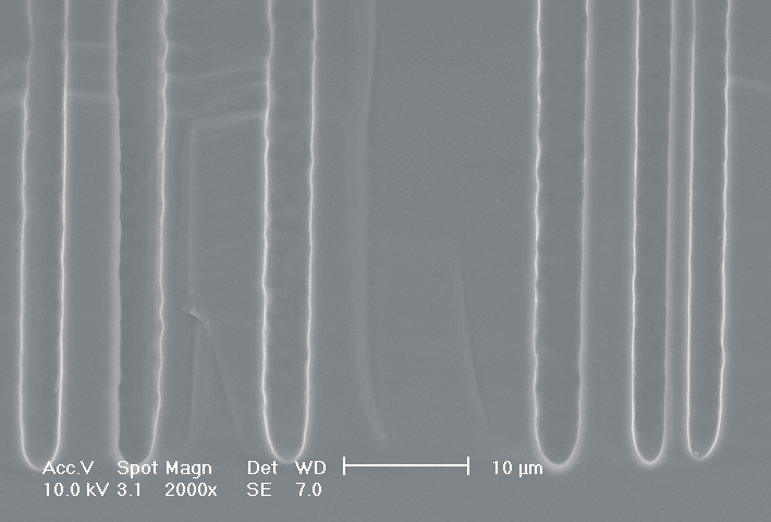
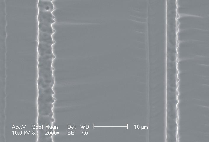
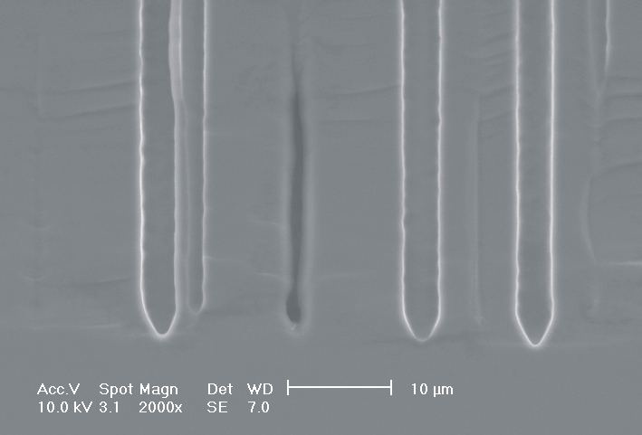
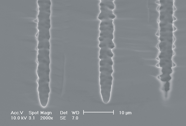
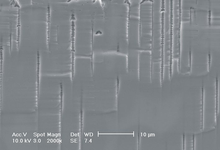
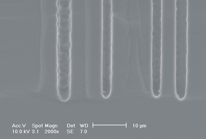
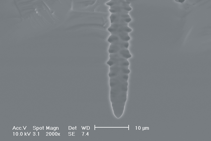
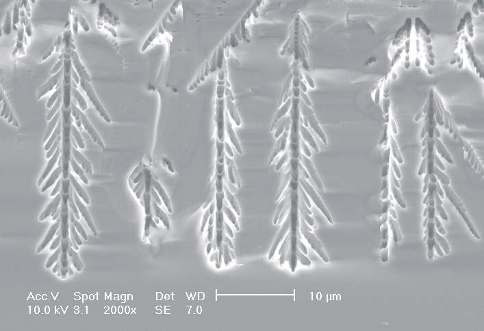
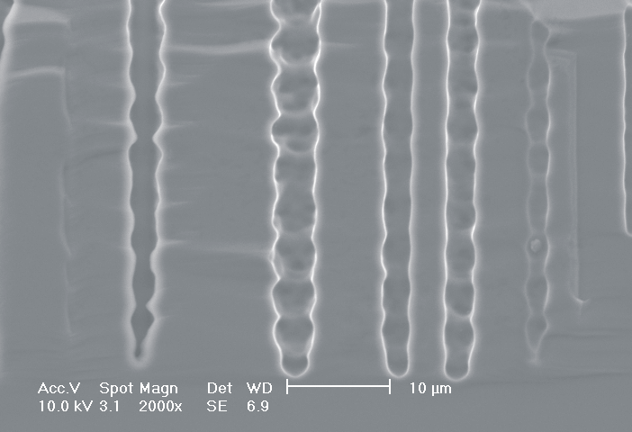
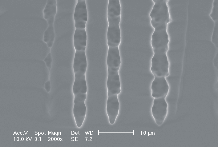
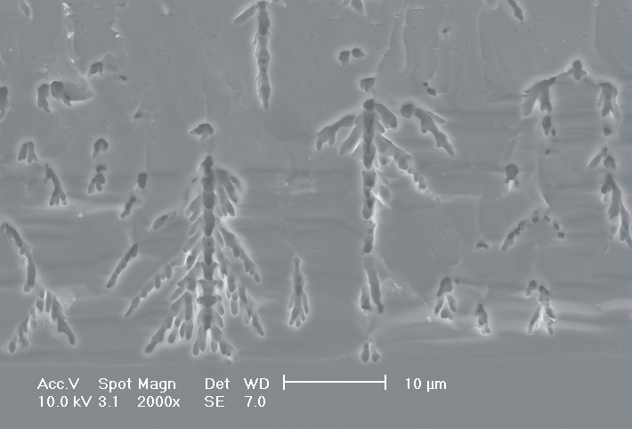
This interplay of different time- and length scales will be discussed for the example given in Fig. 3. Macropores are formed in n-Si with backside illumination. For studying the time dependence of the system, the etch current (controlled by backside illumination intensity) was modulated with different periods: a) no modulation, b) 0.5 min.-, c) 1.0 min.-, and d) 5.0 min. cycle time for the modulation. The doping level (10 Wcm) as well as the HF concentration of 4 wt.-% for row 1 have been optimized to generate stable macropores in the µm range, i.e. all length scales (space charge region width (SCRW), domain size,..) are in the µm range. Consequently this system can only follow very slow diameter modulations, since the corresponding intrinsic time constant does not allow for fast modulations. Increasing the HF concentration, the intrinsic length decreases whereas the SCR width stays constant – the pores are slightly unstable; the sides become wavy with a wave length determined by the intrinsic length scale – cf. Fig. 3.1a) and 3.2a). The oxide of each current burst now is dissolved more quickly, allowing the system to follow higher modulation frequencies. This effect is even more pronounced when the oxidizing part of a current burst is weakened by using an organic electrolyte. Simultaneously with the time scale (now allowing to follow modulation with a 0.5 min. period) the domain size (intrinsic length scale) is reduced drastically, leading to smaller pore diameters. It is graphically shown that the intrinsic length scale of the current bursts can overrule the SCR width, but with the disadvantage of prolific side pores formation and rough pore walls, respectively.
| a) |
|
|
|
| b) |
|
|
|
| c) |
|
|
|
| d) |
|
|
|
| 1) H2O, 4 wt.-% HF |
2) H2O, 7 wt.-% HF |
3) DMF, 4 wt.-% HF |
|
Fig. 3: Modulation of the pore diameter on moderately doped Si (10 W cm) by changing the intensity of the backside illumination: a) no modulation, b) 0.5 min. for modulation period, c) 1.0 min. for modulation period, d) 5.0 min. for modulation period. In an aqueous electrolyte with 4 wt.-% HF the pore diameter can follow only the slowest frequency. With 7 wt.-% the system can follow a 1.0 min- modulation bot not a 0.5 min. modulation. The DMF-system can follow this frequency easily. The intrinsic relaxation time of each electrolyte does not only define the intrinsic length scale of the system but can also be used to stabilize pore growth by a resonance phenomenon seen in 2c). |
|||
Most astonishing are the pores in Fig. 3.3b), since no side pores exist, although for lower modulation frequencies they are very pronounced. This is the first example where we explicitly benefit from and directly demonstrate the intrinsic time constant of the current bursts. Although the modulation frequency is to slow to be perfectly in resonance with the current bursts, the modulation triggers the current bursts to "burn" in phase (comparable to what happens spontaneously in the oscillation regime). Exactly in the phase of oxide dissolution (no charge consumption is possible at the pore tips) the number of offered charges is reduced by the modulated current. Without modulation
these charges would lead to the formation of side pores which is not possible now. This "resonance effect" is typical for stochastic systems with an internal frequency and perhaps the best verification of the current burst model so far.
these charges would lead to the formation of side pores which is not possible now. This "resonance effect" is typical for stochastic systems with an internal frequency and perhaps the best verification of the current burst model so far.
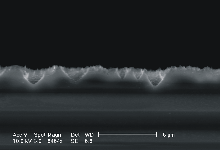
Another example for "electrolyte design" [9] is presented in Fig. 4.
| a) |
 |
b) |
 |
| c) | 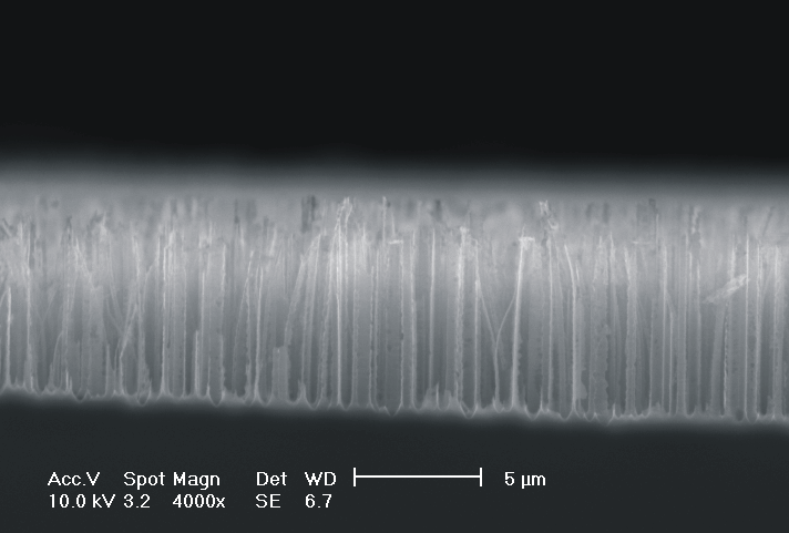 |
d) | 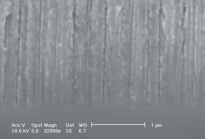 |
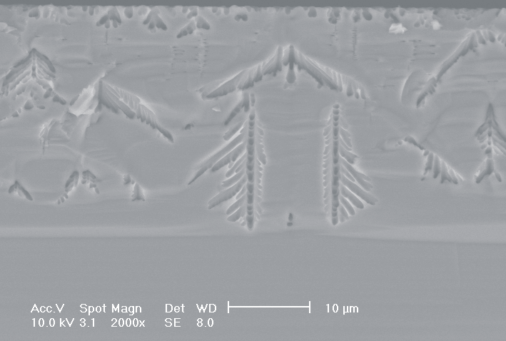
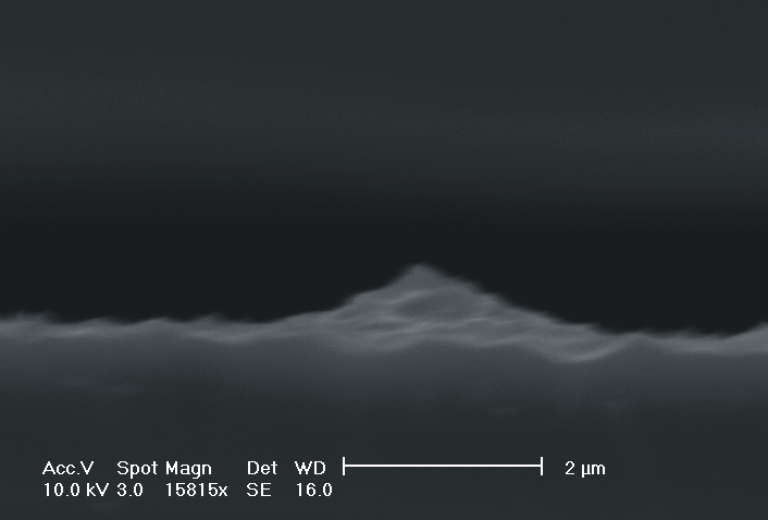
| Fig. 4: The dissolution of highly doped n+-Si (0.02 Wcm) depends extremely on the choice of the electrolyte. Using TMAH as electrolyte (high oxidizing rate, strong H-passivation) we find for different HF concentrations: a) 2 wt-% HF: smooth surfaces with some hillock formation; b) 3 wt.-% HF: rough surfaces; c) 6 wt.-% HF: macropore formation; d) 8 wt.-% HF: mesopore formation. |
|||
Only by changing the HF-concentration, i.e. the internal time constant and therefore the oxide domain size, one can switch monotonically from electropolishing (Fig. 4a)) via macropore formation (Fig. 4b) and c)) to mesopore formation (Fig. 4d)). Even macropores could be formed for the first time in the highly doped n-type Si used, (Fig. 4c)), although the stabilizing length scale (SCR width) of the n+-Si (0.02 Wcm) would only allow for mesopores in aqueous electrolytes. Since in aqueous electrolytes the oxidizing component is not sufficient to overrule this small length scale, we used the strongly oxidizing electrolyte TMAH with different concentrations of HF to control the oxide dissolution. From all electrolytes known to oxidize silicon chemically or electrochemically which we have tested only TMAH (and to some extent CrO3) allowed for the formation of macropores. TMAH is best, probably because it has a strong tendency for H-passivation which is adapted to the strong oxidizing tendency of this electrolyte.
The hydrogen supply is a third independent electrolyte parameter to optimize pore formation but, for lack of space, will not be discussed explicitly in this paper.
Conclusions
The current burst model allows for a deeper insight into the mechanism of pore formation in the silicon HF system and probably in other semiconductor systems as well. This allows to increase substantially the range of stable pores of different morphologies by systematic experiments including control of the pore growth by outside synchronization. By changing only the chemical composition of the electrolyte, one can change e.g. from stable mesopore to macropore growth and vice versa. Extremely stable macropores can be formed, e.g. in p-Si-samples using organic electrolytes which would not grow in aqueous electrolytes. A large number of experimental data which support this model are be presented in several papers within this proceedings [10-12].
Acknowledgement
We are indebted to our colleagues form the MPI-MSP in Halle and S. Langa and Dr. I. Tiginyanu form the Technical University of Moldova for fruitful discussions. This work was supported by the Deutsche Forschungsgemeinschaft (Förderungsnummer: FO 258/1-2).
References
[2] J. Carstensen, R. Prange, G. S. Popkirov, H. Föll, Appl. Phys. A., 67, 459 (1998)
[3] G. Hasse, J. Carstensen, G. S. Popkirov, H. Föll, Mat. Sci. Eng., B 69 – 70, 188 (2000)
[4]V. Parkhutik, E. Matveeva, R. Perez, J. Alamo, D. Beltrán, Mat. Sci. Eng., B 69 – 70, 553 (2000)
[5]S. Rönnebeck, S. Ottow, J. Carstensen, H. Föll, J. Electrochem. Soc. Lett., 2,126 (1999)
[6] V. Lehmann, J. Electrochem. Soc., 140, 2836 (1993)
[7] V. Lehmann, U. Gösele, Adv. Mat., 4, 114 (1992)
[8] M. J. J. Theunissen, J. Electrochem. Soc., 119, 351 (1972)
[9] M. Christophersen, J. Carstensen, A. Feuerhake, H. Föll, Mat. Sci. Eng., B 69-70, 194 (2000)
[10] H. Föll, J. Carstensen, M. Christophersen, G. Hasse, this proceedings(2000)
[11] G. Hasse, M. Christophersen, J. Carstensen, H. Föll, this proceeding (2000)
[12] M. Christophersen, J. Carstensen, H. Föll, this proceeding (2000) (2000)
