 |
Know your numbers and relations for visible light! |
|
For the propagation of light:
use the wave model
For the generation and
disappearance (= absorption) of light:
use the photon model
|
Snellius law:
n = sina/sinb with a,
b the angle of incidence
or propagation, resp. |
|
|
 |
Wavelengths: l
» 400 nm - 800 nm. | |
| |
lmat = l0/n. |
|
|
 |
Frequency: n» 10 15
Hz. | |
|
 |
Index of refraction: n = er½
» 1,5 - 2,5 | |
|
 |
Energy E » 1,8 eV - 3,2 eV. |
|
|
 |
Dispersion relation: c0 = n l0 = 3 ·
108 m/s
cMat = n l0/n(l) |
|
| |
| |
| |
 |
Know yout basic equations and terminology |
|
 |
Coherent monochromatic plane wave
E and H perpendicular and in phase |
|
| | |
| |
| | |
E(r,t)
H(r,t) | = |
E0
H0 |
· exp{i(kr –wt)}
|
|
| |
| |
| |
|
|
 |
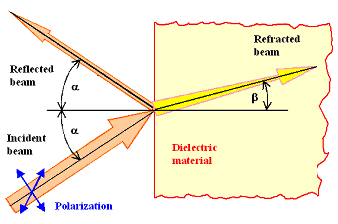
Reflection always with "angle in" =
"angle out".
| |
|
 |
Refraction is the sudden "bending" or "flexing"
of light beams at the interface | |
|
 |
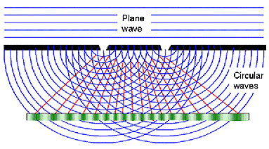
Diffraction is the continous "bending" of light beams around corners;
interference effects. | |
| | |
| |
|
 |
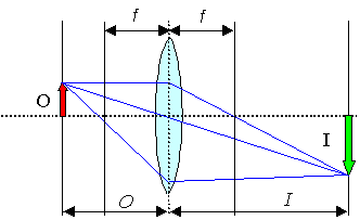
Geometric optics
Key paramters |
|
|
|
 |
Focal length f and
numerical aperture NA of lenses,
mirrors. | |
|
 |
Image formation by simple geometric constration |
|
|
 |
Various aberrations (spherical. chromatic, astigmatism, coma, ...) limit performance. |
|
|
| |
| |
 |
Wave optics
Huygens principle: and interference |
|
|
|
 |
Ultimate limit to resolution | |
| | |
| |
| | |
| |
| |
| |
|
 |
Know your basic types of waves: |
|
|
 |
(Running, coherent, monochromatic) plane wave.
| |
|
 |
Standing waves = superposition of plane waves. |
|
|
 |
Incoherent, multichromatic real waves |
|
| |
| |
 |
Relation s between electrical field E, magnetic field H
and Poynting vector (energy flow vector) S = E × H |
|
|
|
|
| [Welect; magn] |
= |
[Ws m–3] |
|
| E0 |
= |
æ
ç
è
|
mrm0
ere0 |
ö
÷
ø |
½ |
· H0 |
= |
Zw · H0 |
|
|
| |
| |
| |
| |
| |
| |
|
|
|
This equation links energy flow (easy in photon picture)
to field strength in wave picture. |
|
|
 |
Zw = wave impedance of the medium.
Zw(vacuum) = 376,7 W |
|
| |
| |
| |
 |
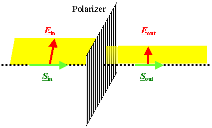
Polarization = key to "advanced" optics.
Simple case: linear
polarization. | |
|
|
 |
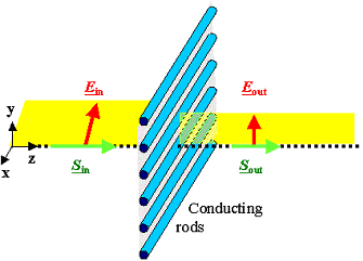
Plane of polarization contains E-vector and S (k)
vector. | |
|
 |
Any (coherent) wave is polarized but net polarization
of many waves with random polarization is zero! | |
|
 |
Light intensity (µ
E2) between polarizers at angle a scales with (cosa)2. | |
 |
General case: elliptical polarization; important
are the two extremes: linear and circular polarization. |
|
|
 |
For circular polarizaiton the E-vector rotates on a circle while moving
"forward". This results from a superposition of two plane waves with E-vectors ar right angles
and a phase difference of p/2. |
|
|
 |
Technically important (3-dim Cinema; Lab optics) |
|
 |
The task:
Calculate and understand intensities, angles, phases, polarization
and attenuation (damping) of the various light beams shown from the materials properties |
|
|
|
 |
Still assuming a perfectly flat surface |
|
 |
First step: Decompose impinging light into two waves with polarization in he interface
plane (TE case) or at right angles (TM case) | |
|
 |
Energy conservation yields for the intensities: |
|
|
|
| |
|
| |
| |
 |
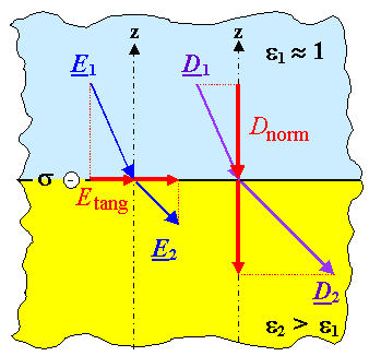
Boundary conditions as shown in the figure involve the "dielectric constant
e and thus the so far only relevant material property. |
|
|
|
 |
Considering energy (proportional to E2) and momentum (proportional
to k2") conservation for the TE and TM case separately yields the Fresnel equations
that provide the answers to the questions above | |
| |
 |
A wealth of insights and relations follow, e.g. or field strength E or intensities
I: | |
| | |
Eref
Ein |
| = – |
n – 1
n + 1 |
| | | |
| | |
Iref
Iin | |
| = |
æ
ç
è |
n – 1
n + 1 |
ö
÷
ø |
2 |
|
| |
| |
 |
one consequence as example for the power of these equations: n = 2
means that almost 10 % of the intensity will be reflected, implying that for optical instruments you must
provide some "anti-reflection" coating. | |
| | |
| |
 |
Using the complex (and frequency dependent "dielectric constant e(o) = e' + ie''
yields the complex index of refraction | |
| n2 | = |
1
2 |
æ
ç
è |
æ
è |
e' 2 + e'' 2 |
ö
ø |
½ |
+ e' |
ö
÷
ø |
| k2 | = |
1
2 |
æ
ç
è |
æ
è |
e' 2 + e'' 2 |
ö
ø |
½ |
– e' |
ö
÷
ø |
|
|
| |
| |
|
 |
The imaginary part k describes the attenuation (damping)
of the transmitted wave in the material. | |
| | |
| |
 |
Not so perfect materials and properties like specular and diffuse Reflection,
transparency, Translucency, Opacity. | |
|
|
 |
Light is scattered at small things in all directions and the scattering of light
is the major topic encountered if we look at not-so-perfect materials |
|
|
 |
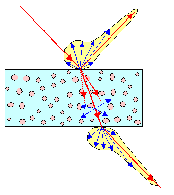
The picture illustrates:
Specular and diffuse reflection at the surface.
Scattering
of the transmitted light (running in different directions) at defects or imperfections contained in the material (fat droplets
in milk, air bubbles in glass, ...).
Specular and diffuse reflection at the internal surface the light is coming out
off. This is described by a (different) polar diagram characterizing this surface. |
|
 |
Scatter mechanism depend on the size lsca of the scatterer"
relative to the wavelength:
lsca << l: The extreme case would be scattering at single atoms
or molecules. Proper nanoparticles also belong into this group. This
kind of scattering is called Rayleigh
scattering
lsca >>l: No problem, we covered that already. Just look at any
part of the sample by itself.
lmat »
l: Now we have a problem. What will happen in this case is difficult to deal with and no
general rules apply. This kind of scattering is called Mie
scattering | |
| | |
| |
|
 |
Processing light
with, for example, conventional lenses, mirrors and
prism, anti-reflection coatings | |
|
|
 |
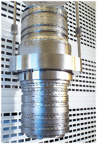
Even simple light processors like lenses (and the rest from above) might be extremely
complex materials engineering products today. Just look at the picture of a (by now (2019) outdated lens for microelectronic
lithography- | |
 |
Polarizers, diffraction gratings and filters add another layer of complexity. |
|
|
 |
The list goes on, with, e.g. phase shifters and whatever is needed for doing holgraphy or... |
|
|
 |
Laser "beam forming", modulation, fultr-high speed detection, ... |
|
|
| |
|
© H. Föll (Advanced Materials B, part 1 - script)
